
Previous
Next
Johnson Controls AMPS-24E Addressable Power Supply Technical Guide
General Description
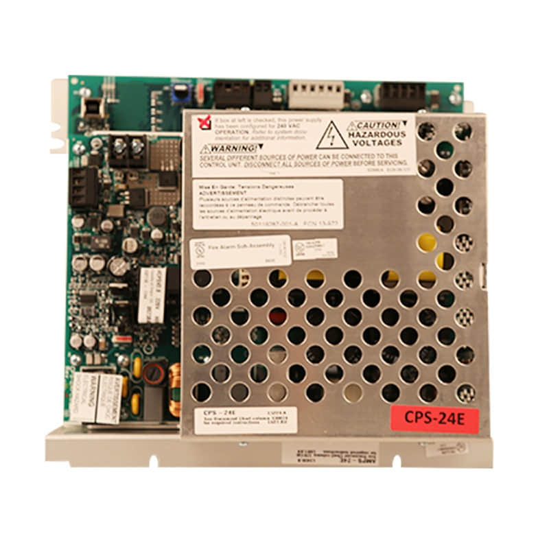
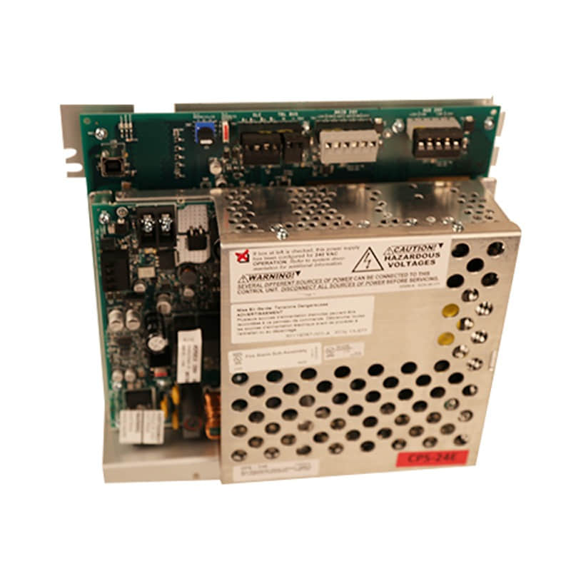
The Johnson Controls AMPS-24E is an intelligent, addressable system power supply with an integrated standby battery charger and multiple regulated 24VDC outputs. Designed to integrate seamlessly with FlashScan® and CLIP (Typical Loop Interface Protocol) fire alarm control panels (FACPs), it serves as a primary electrical backbone for life safety networks.
The AMPS-24E features an isolated Signalling Line Circuit (SLC) interface that occupies four loop addresses to report vital power faults, battery conditions, and AC line status. When managing complex power distribution across high-capacity cabinets, the unit pairs cleanly with structural cabinet accessories and internal bus components such as the Johnson Controls C878-10, Johnson Controls C878-33, and Johnson Controls G339-10 to establish a secure, compliant installation framework.
Technical Specifications
| Parameter | Specification Details |
| Model Designation | AMPS-24E Addressable Power Supply |
| Primary Input Voltage | 220–240 VAC, 50/60 Hz |
| Maximum Input Current | 2.5 A |
| Main Power Output (TB3) | 240VAC, 50/60Hz input; filtered 24VDC outputs across multiple terminals |
| Auxiliary & Secondary Outputs (TB6) | 5VDC (1.0A max) and 24VDC (1.0A max) regulated options |
| Battery Charging Capacity | Sealed lead-acid batteries from 7 AH up to 200 AH |
| Selectable Charging Current | 1.0 A, 2.0 A, or 5.0 A configurations |
| Operating Temperature Range | 0 C to 49C (32F to 120F) |
| Environmental Humidity | Up to 93% relative humidity ($\pm2\%$ at $32\text{ }^\circ\text{C} \pm2\text{ }^\circ\text{C}$) |
Detailed Features & Capabilities
Dual Protocol Operation: Fully compatible with both FlashScan and CLIP FACP communication formats.
Isolated SLC Interface: Communicates power supervision faults safely back to the main control panel without electrical interference.
Comprehensive Fault Monitoring: Continuously tracks AC power loss, brownout conditions, battery open/short circuits, and charger status.
Onboard USB Programming Port: Features a USB Type B connector for streamlined parameter configuration and firmware management.
Typical Applications
Commercial Office Complexes: Reliable power distribution for multi-zone notification appliance circuits.
Industrial Manufacturing Plants: Robust performance across extensive, harsh environmental footprints.
Healthcare Facilities: Uninterrupted power supervision required for life safety and emergency voice evacuation systems.
Educational Campuses: Centralized backup power for sprawling network architectures.
Installation & Wiring Procedure
Site Preparation: Select a dry, climate-controlled location that allows unhindered maintenance access.
Unit Mounting: Securely mount the AMPS-24E inside a compatible enclosure (such as CAB-4 or BB series backboxes) using approved mounting hardware. Ensure proper spacing for thermal ventilation.
Power & Bus Wiring: Connect AC power leads to terminal block TB3 and wire auxiliary outputs according to system blueprints.
Cabinet & Component Integration: Secure internal power distribution modules and ground straps utilizing approved hardware components—such as the Johnson Controls C878-10, C878-33, and G339-10—to maintain rigid mechanical stability and correct electrical bus continuity.
Battery Termination: Connect backup batteries matching correct polarity and verify jumper settings for the desired charging current.
System Commissioning: Power on the unit, simulate AC failure conditions to test brownout reporting, and use the USB port to finalize software configuration.
Frequently Asked Questions (FAQ)
Q1: What communication protocols are supported by the Johnson Controls AMPS-24E power supply?
A: It is fully compatible with both FlashScan and CLIP (Typical Loop Interface Protocol) fire alarm control panel communication formats.
Q2: What is the battery charging capacity and selectable current range for the AMPS-24E?
A: It supports sealed lead-acid batteries ranging from 7 AH up to 200 AH, with selectable charging current configurations of 1.0 A, 2.0 A, or 5.0 A.
Related Part Numbers, System Compatibility & Hardware Accessories
Johnson AMPS-24: Alternative model variant configured for lower voltage applications.
Johnson NCA Network Control Annunciator: Auxiliary display unit for enhanced remote system monitoring.
System Cabinets & Bus Distribution Accessories
When organizing system architecture within central control cabinets, technicians rely on specialized hardware components to manage power rails and internal interface connections:
Johnson Controls C878-10 & C878-33: Standardized power distribution and cabinet mounting brackets designed to secure secondary modules and maintain clean wiring topologies within large-scale enclosures.
Johnson Controls G339-10: Specialized bus component and hardware accessory utilized to ensure reliable grounding, structural integrity, and electrical isolation across system power supplies.
If you require official engineering datasheets, wiring schematics, or bulk quotation support for the AMPS-24E and its cabinet accessories, please contact our technical support team.
Previous: ACM-24AT