


Previous
Next
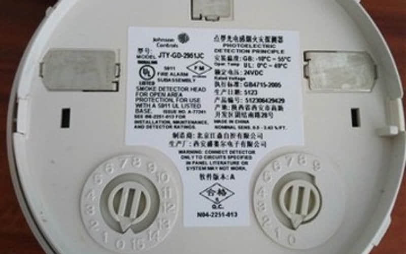
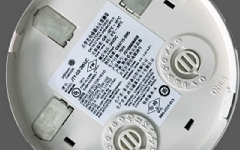
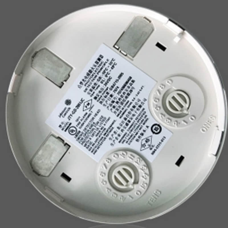
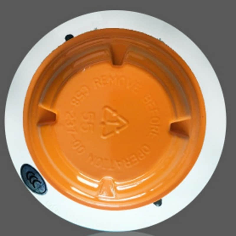
Johnson Controls JTY-GD-2951JC Smoke Detector | In Stock
Availability: In Stock | Condition: 100% Original Brand New | Warranty: 1 Year
General Description
The Johnson Controls JTY-GD-2951JC is an advanced, addressable photoelectric smoke detector engineered to enhance commercial and industrial fire safety. Designed with a state-of-the-art optical sensing chamber, it delivers rapid response to a wide range of combustion sources while effectively minimizing nuisance false alarms. Fully compatible with FlashScan® communication protocols, this smoke detector ensures seamless integration and reliable status reporting for critical fire alarm networks.
Technical Specifications of Johnson Controls JTY-GD-2951JC
Model Part Number: JTY-GD-2951JC
Device Type: Addressable Photoelectric Smoke Detector
Operating Temperature Range: 32°F to 120°F (0°C to 49°C)
Humidity Range: 10% to 93% (non-condensing)
Operating Voltage / Power Supply: 24V DC loop power
Standby Current: Low power consumption design
Communication Protocol: FlashScan® compatible
Addressing Method: Rotary decimal addressing (01 to 159)
Key Features & Operational Benefits
Advanced Optical Sensing Chamber: Engineered to detect early-stage smoke particles from various combustion types.
Dual LED Indicators: Provide a 360° viewing angle; steady green indicates normal standby, while solid red signals an active alarm.
Built-in Test Switch: Allows quick functional testing using an external magnet.
Walk Test Functionality: Simplifies system verification with visible address display during diagnostic testing.
Environmental Resistance: Sealed construction prevents backpressure issues and ensures reliable performance across diverse conditions.
Built-in Tamper Resistance: Designed to deter unauthorized removal or physical tampering.
System Compatibility & Applications
The JTY-GD-2951JC integrates smoothly into standard fire alarm control panels supporting FlashScan loops. Typical deployment environments include:
Commercial office buildings and retail complexes
Industrial facilities and manufacturing plants
Educational institutions and campuses
Healthcare environments and hospitals
Modern residential and multi-story structures
Installation Guidelines
Preparation: Review local fire codes, gather required tools, and confirm system compatibility before installation.
Mounting: Attach the detector securely to a standard junction box at recommended heights based on engineering standards.
Wiring: Connect power and communication lines following the official wiring diagram, ensuring correct polarity using SEMS terminals.
Addressing: Configure the unique device address using the built-in rotary decimal switches to match the control panel programming.
Testing: Execute a functional test using the magnet test switch or walk test mode, observing the LED status indicators to verify operation.
Frequently Asked Questions (FAQ)
Q: Is this Johnson Controls JTY-GD-2951JC detector brand new and original? A: Yes, we supply 100% brand-new original Johnson Controls fire safety and industrial automation components.
Q: What control panels are compatible with the JTY-GD-2951JC? A: It is compatible with systems supporting FlashScan communication protocols and rotary decimal addressing from 01 to 159.
Related Fire Safety & Industrial Parts
Browse our inventory for more Honeywell and Johnson Controls Fire Alarm Parts.
Request a Quote for JTY-GD-2951JC
Need bulk quantities, official datasheets, or fast international shipping? Contact our professional sales engineering team today for competitive pricing and lead times.
Previous Related Sensor:
Check out the matching TW-BD-5951JC Intelligent Temperature Sensor for complete fire detection system coverage.