
Previous
Next
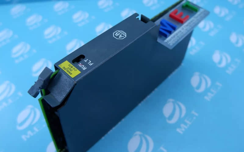
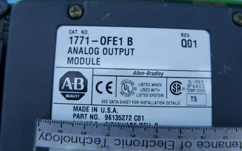
Allen Bradley 1771-OFE1 Analog Input Module
General Description of 1771-OFE1 Analog Input Module
The Allen Bradley 1771-OFE1 Analog Input Module is part of the 1771 I/O series designed to handle analogue output tasks in programmable logic controller (PLC) systems. This module converts digital signals into analogue outputs, making it suitable for various industrial applications. The 1771-OFE1 supports up to four differential voltage outputs and can handle multiple voltage ranges, ensuring adaptability across different operational requirements.
Technical Specifications
l Output Type: Differential Voltage
l Number of Outputs: 4
l Voltage Output Range: ±10V DC, 0 to 10V DC (configurable)
l Current Output Capability: Not applicable (for current output, see 1771-OFE2)
l Data Format: Binary or BCD values
l Power Requirements: Powered via the I/O chassis backplane
Detailed Features
1. Differential Outputs: Each output is isolated to prevent interference, allowing for stable and accurate signal transmission.
2. Configurable Scaling: Users can select scaling options to convert input values into engineering units.
3. Block Transfer Programming: Supports block transfer write (BTW) and block transfer read (BTR) instructions, facilitating efficient data handling.
4. User-Friendly Interface: The module features clear status indicators for RUN and FAULT conditions, aiding in quick diagnostics.
Applications of 1771-OFE1 Analog Input Module
The 1771-OFE1 Analog Input Module is ideal for a wide range of applications, including:
A. Process Control Systems: Used to control temperature regulation, flow control, and pressure monitoring.
B. Industrial Automation: Integrates with various sensors and actuators to automate machinery and production lines.
C. Data Acquisition Systems: Collects data from various sources for analysis and monitoring.
D. Robotics Control Systems: Provides precise control signals to robotic devices for accurate movement and operation.
Installation
l Preparation:
Ensure the I/O chassis is powered down before installation. Verify that the power supply meets the required specifications.
l Mounting the Module:
Insert the 1771-OFE1 module into an available slot in the compatible I/O chassis (e.g., 1771-A1B, A2B, A3B).
Ensure that the module is securely seated in the slot.
l Wiring Connections:
Connect field devices to the module using the wiring arm provided. Follow the wiring diagram included in the installation manual.
Recommended cable length for voltage signals should not exceed 50 feet to minimize signal degradation.
l Configuration:
Set configuration jumpers on the module according to the desired voltage range for each output channel. The module ships with jumpers set for +10V by default.
Ensure that all connections are tight and secure before powering up.
l Power Up:
Restore power to the system and observe the status indicators on the module.
Perform initial diagnostics using block transfer read commands to verify proper operation.
l Testing:
Conduct functional tests on connected devices to ensure they respond correctly to output signals from the module.
Related Part Numbers
The following part numbers are related within the same series:
l 1771-OFE2: The current output version of this module has similar features.
l 1771-OFE3: Another variant supporting different current ranges.
l 1771-A2B: Universal I/O chassis compatible with these modules.
Previous: Allen Bradley 1734-IA2 Module