
Previous
Next
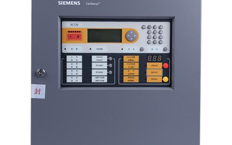
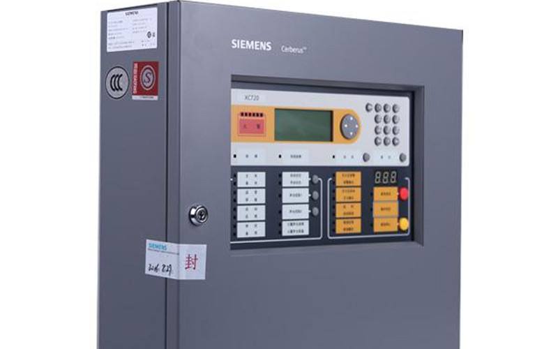
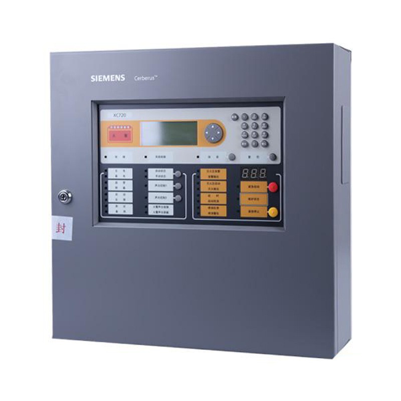
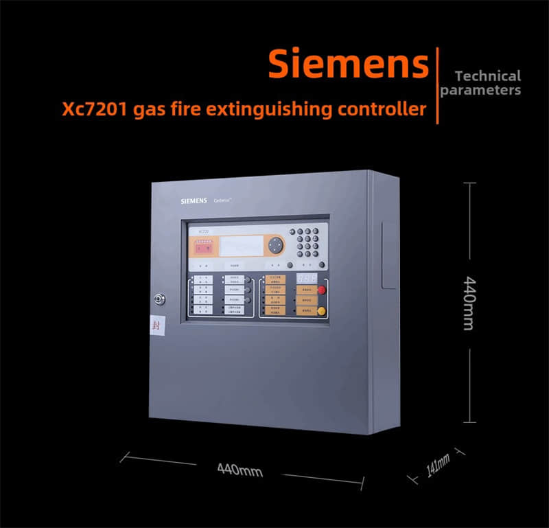
Siemens XC7201 Gas Fire Extinguishing Controller | Original In Stock
Condition: 100% Original Brand New
Availability: In Stock (Ready to Ship Worldwide)
Lead Time: 3-5 Working Days
Warranty: 1 Year
1. Overview of the XC7201 Gas Fire Extinguishing Controller
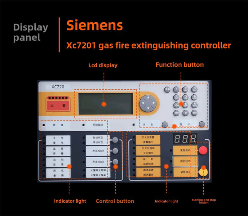
A. The XC720 and gas fire extinguishing controllers are specifically designed to control Fire extinguishing equipment in key protection zones and start on-site area monitoring and auxiliary alarm units.
B. The XC720 has fire detection and gas fire extinguishing control functions, allowing for the fire alarm and gas fire extinguishing control of a gas extinguishing zone. It can be used for automatic or manual gas fire extinguishing.
C. The XC720 can be connected to addressable heat detectors, smoke detectors, infrared flame detectors, linear beam smoke detectors, aspirating smoke detectors, and other on-site devices such as emergency stop/start buttons, Sound and light alarms, Soundas discharge indicator lights.
D. The XC720 design complies with relevant national standards GB4717-2005 "Fire Alarm Controllers" and GB16806-2006 "Fire-fighting Linkage Controllers" regarding gas fire extinguishing controllers.
2. Features of the XC7201 Gas Fire Extinguishing Controller
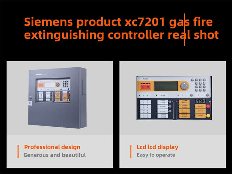
l Professional appearance design, elegant and beautiful.
l Leading technology with Siemens international design.
l High-speed 32-bit CPU for fast operation.
l Outstanding system reliability design with unique 7×24-hour solenoid valve and circuit monitoring.
l LCD has a simple operation and is clear, intuitive, and easy to query.
l It has a vast storage capacity and can record up to 30,000 historical records, including 1,000 fire alarm records; events and operations during operation are fully recorded.
l When no operations occur within the set time, and there are no alarms, linkages, or fault information, the controller automatically enters screen saver mode to extend the lifespan of the LCD screen; when an event or operation occurs, the screen automatically lights up, displaying the event and linking the relevant devices according to the logical relationship.
l Real-time event printing capability.
l Each controller controls one fire zone.
l Each controller has 7 programmable inputs and 11 outputs.
l Each controller can connect up to 126 on-site devices.
l The controller has three user levels: Level 1, Level 2, and Level 3. Different operations are available under different user levels and are protected by passwords.
l Long standby time, with automatic switchover to backup power when the main power is lost.
l Large digital tube display for delay time, obvious and intuitive.
l Protection to prevent misoperation for important function buttons.
l All wiring terminals are pluggable, with clear markings for easy installation, debugging, and maintenance.
l Simple and fast debugging, with built-in gas fire extinguishing programs to save time on configuration.
l Automatic mapping of on-site devices.
l The controller allows detectors' sensitivity to be adjusted, automatically adapting to environmental changes to improve fire alarm reliability significantly.
l Direct programming is done on the controller, and fast programming is done via a computer.
l On-site components are labeled with detachable coding stickers for easy engineering debugging.
l Compliant with national standard GB4717-2005 "Fire Alarm Controllers."l Compliant with national standard GB16806-2006 "Fire-fighting Linkage Control Systems."
l According to the product design, the insulation resistance between external live terminals and the chassis is less than 20 megaohms, and external live terminals are not required to be insulated.
3. XC7201 Gas Fire Extinguishing Controller Parameters
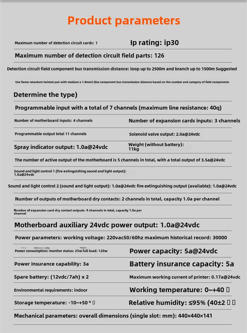
ü Maximum number of detection loop cards: 1
ü Maximum number of on-site components per detection loop: 126
ü Detection loop bus transmission distance: Up to 2500 meters for the loop and 1500 meters for the branch. Recommended use of flame-retardant twisted pair cables with Φ≥1.0mm² (the transmission distance depends on the number and type of on-site components).
ü 7 programmable inputs (maximum line resistance: 40Ω).
ü Mainboard input count: 4
ü Expansion card input count: 3
ü 11 programmable outputs
ü 5 active outputs on the mainboard, total output 3.5A @ 24VDC
ü Solenoid valve output: 2.0A @ 24VDC
ü Discharge indicator light output: 1.0A @ 24V
Solenoid valve output: 2.0A @ 24VDC
Discharge indicator light output: 1.0A @ 24VDC
Sound and light alarm output: 1.0A @ 24VDC
Fire extinguishing output (configurable): 1.0A @ 24VDC
ü 2 dry contact outputs on the mainboard, each with a capacity of 1.0A
ü 4 dry contact outputs on the expansion card, each with a capacity of 1.0A
ü 1 auxiliary 24VDC power output on the mainboard: 1.0A @ 24VDC
ü Maximum historical record: 30,000
ü Power supply parameters:
ü Operating voltage: 220VAC 50/60Hz
ü Power consumption:
ü Standby: 25W
ü Full load: 120W
ü Power supply capacity: 5A @ 24VDC
ü Power supply fuse capacity: 3A
ü Battery fuse capacity: 5A
ü Backup battery: (12VDC/7Ah)×2
ü Maximum working current for the printer: 0.17A @ 24VDC
ü Mechanical parameters:
ü Dimensions (mm): 440×440×141
ü Weight (excluding batteries): 11kg
ü Environmental parameters:
ü Operating temperature: 0~+40℃
ü Storage temperature: -10~+50℃
ü Relative humidity: ≤95% (40±2℃)
ü IP rating: IP30
ü Environmental requirement: Indoor
Previous: Honeywell C7027A1049