1. Introduction
In industrial operations, downtime equals lost production and revenue. When a burner control system triggers a lockout, maintenance engineers face immense pressure.
Beyond the noisy, hot environment, the challenge is reading hundreds of pages of technical documents. The goal is to find the root cause fast. Every second of delay affects the bottom line.
In reality, Honeywell burner control troubleshooting is a complex task. Manufacturer manuals are detailed and long. They include dense electrical schematics and technical jargon. This can be impractical in a high-pressure field environment.
This guide translates complex diagnostic logic into a standard operating procedure (SOP). Whether you face a routine lockout or unclear flash codes, we will guide you through these manuals. We cut through technical clutter to reduce downtime and boost your honeywell boiler control error codes maintenance efficiency.
2. The Anatomy of Honeywell Error Codes and how to diagnose honeywell burner faults
Fault codes are more than just error messages; they are the language between the system and the technician. Mastering this language is the key to evolving from a reactive "fixer" to a proactive "system diagnostician."
2.1 Flame Safeguard Control Maintenance Codes: Interpreting Analog Signals
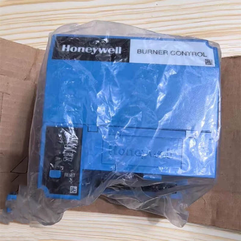
Flash codes are common in legacy models such as the Honeywell RA116A Protectorelay and the R8184G series. These devices lack digital displays and instead communicate status via a red light on the "Safety Switch."
Mechanism: The internal microprocessor monitors flame establishment, ignition sequences, and power stability. When a logic error occurs, it triggers an electromagnetic pulse, causing the LED to flash at specific intervals.
Interpretation: Precision is vital. For example, “3 flashes, then a pause” often means “ignition failure.”
“Continuous flashing” often means a “flame detector fault.”
Field Application: When the safety switch flashes, consult the specific model's manual for the "Flash Code" table. Never guess based on experience, as interpretation varies by model.
2.2 Display Codes: Direct Digital Feedback
Modern smart controllers (such as advanced industrial control modules) offer more intuitive diagnostics.
Mechanism: The controller outputs alphanumeric codes directly (e.g., E10, F7).
Interpretation: Simply record the code and look it up in the manual’s "Error Code Index."
Diagnostic Logic: Flash codes are "analog signals" that need you to watch and count. Display codes are "digital signals" that give direct references. This significantly shortens the time from diagnosis to action.
Manual Navigation: Using Flowcharts to Eliminate Variables
The core design of Honeywell manuals is not for cover-to-cover reading, but for logical screening via Flowcharts.
Binary Decision Making: Flowcharts break down complex fault trees into "Yes/No" steps, preventing cognitive overload.
Hierarchical Elimination: Each step eliminates one or more variables, preventing unnecessary hardware replacement.
Cost Efficiency: Many lockouts result from low-cost issues like a dirty flame detector. Flowcharts guide you to check these first, rather than replacing expensive modules prematurely.
Field Case: Honeywell R8184G Diagnostic SOP
In a 2025 petrochemical site, an R8184G controller locked out. Our team utilized the flowchart:
Step 1 (Environment): Checked the C554 Cad Cell. "Is the cell dark when the burner is off?" "No," stray light is the culprit—no circuit work required.
Step 2 (Function): "Does the burner ignite then lock out?" the ignition system is functional, pointing to flame signal intensity or sensor alignment issues.
3. Step-by-Step Manual Reading Guide for Industrial Burner Control Repair
Manuals are tools for retrieval, not narrative. Follow this systematic approach:
3.1 Model Verification
Never skip this. Honeywell’s product line ranges from the RA116A Protectorelay to the RM7800 series.
Check the Label: Note the full model number and suffix (e.g., the "G" in R8184G). Suffixes signify different safety levels and logic.
Generation Identification: Different product generations (Electromechanical vs. Solid-State vs. Microprocessor) have vastly different diagnostic paths.
Authority: Use the official Honeywell/Resideo PDF and the Honeywell RM7800 troubleshooting guide. For example, see document #65-0089 for the RM7800 series. Retrieve documents from official databases like ManualsLib to ensure you are using the correct revision.
3.2 Reading Status Information
Before a lockout occurs, the controller transmits status updates.
Purge: If the motor runs but the ignition sequence fails, focus on the air pressure switch or limit circuit.
Ignition: If it fails here, check the transformer, fuel valves, and flame signal.
Field Tip: Maintain a Log: Keep a field record of codes, status phases (Purge/Ignition), and measurements. This history is your "passport" to expedited support if you eventually contact a manufacturer engineer.
3.3 Following the Diagnostic Path
Troubleshooting Matrix: Use these to check causes by probability. The matrix prioritizes high-frequency/low-cost fixes (e.g., sensor cleaning) before suggesting module replacement.
Flowchart Navigation: Strictly follow the binary path. Even if a step like "Is there 120V at the thermostat input?" seems trivial, do not bypass it.
4. Safety First & Common Pitfalls
4.1 LOTO (Lockout/Tagout)
Before touching any high-voltage electrical components, you must disconnect power and execute a LOTO procedure. Burner systems contain stored energy (capacitors, pressurized gas, oil). Never assume a system is safe without verifying isolation.
4.2 Avoid Blind Reset
A lockout is a safety mechanism to prevent explosions. Resetting without finding the root cause is like "pouring fuel on a fire."
If unburned fuel has built up, the next start could be catastrophic.
4.3 Common Pitfalls
Ignoring Model Specs: Using the wrong manual is more dangerous than having no manual.
Neglecting Status Info: Always note the cycle stage before looking for error codes.
Relying on Intuition: Always follow the manual’s flow; intuition is a common cause of missed low-cost fixes.
Maintenance While Running: Never adjust or inspect while the system is powered/operational.
4.4 The Necessity of the Digital Multimeter
A multimeter is non-negotiable for validating manual conclusions.
Use it to: Verify 120V input, measure C554 Cad Cell resistance, and test limit switch continuity.
Safety Rule: Use CAT III or CAT IV-rated equipment. Follow: Disconnect power → Connect probes → Re-energize → Measure.
5. When to Escalate to Field Application Engineers (FAE)
If you have tried all manual steps, or you see a “High-Risk Operation,” escalate to the manufacturer.
Examples include firmware flashing, core module replacement, or internal chip errors like “INT_AD/INT_DD.”
Efficient Support Request Package:
Identification: Model, Serial Number, and Firmware version.
Context: The status phase at the time of lockout (e.g., "Locked during Purge").
Data: Your measured voltage/resistance readings and diagnostic steps taken.
Visuals: High-resolution photos of the error code and affected hardware.
Why Choose YMZDCS?
We provide high-precision industrial components from Honeywell, Siemens, Emerson, ABB, and Yokogawa.
Why partner with us?
Accuracy: We verify every specification to prevent costly procurement errors.
Reliability: We ensure authentic, high-quality sourcing for your critical systems.
Global Logistics: We handle complex documentation and safe delivery from Xiamen.
Proactive Service: We go beyond sales to support your operational success.
Professional sourcing, simplified.
For more, please refer to https://www.ymzdcs.com
Connect & Download ResourcesNeed more technical resources? Follow my work and download industrial SOPs on these platforms:
[PDF Cheat Sheet] Download this Honeywell SOP on
SlideShare Scribd [Technical Community] Connect with me on
LinkedIn