
Previous
Next
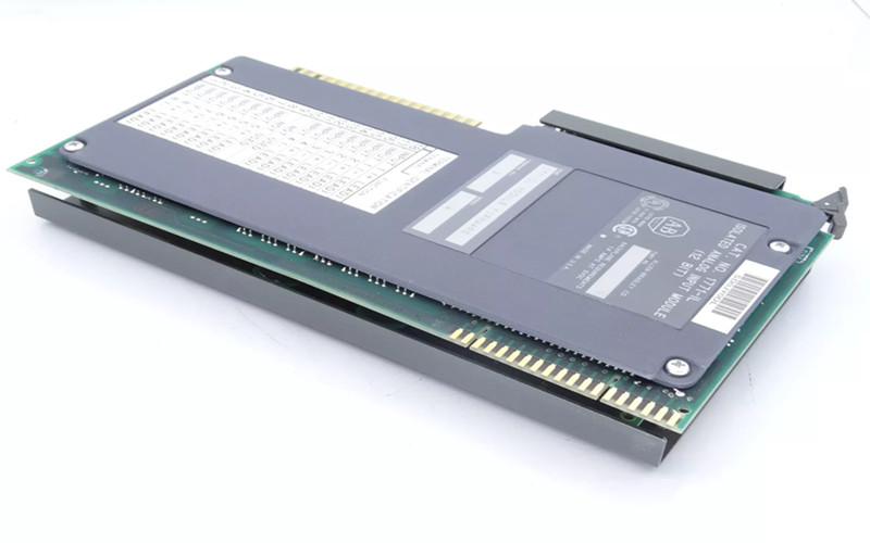
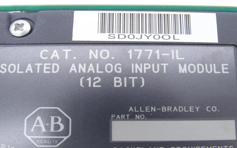
Allen-Bradley 1771-IL PLC Module
General Description:
The Allen-Bradley 1771-IL is designed for use with the PLC-5 family of programmable controllers. This module provides a versatile solution for interfacing with various analog signals, enabling precise data acquisition and control in industrial automation applications.
Technical Specifications of 1771-IL PLC Module :
l Manufacturer: Rockwell Automation
l Brand: Allen-Bradley
l Part Number: 1771-IL
l Type: Isolated Analog Input Module
l Input Channels: 16 single-ended or 8 differential inputs
l Input Ranges: User-selectable (voltage: 1-5V, 0-5V, -5 to +5V; current: 4-20mA, 0-20mA)
l Communication Method: Block transfer (BTW and BTR)
l Power Requirements: 750 mA from the backplane
l Operating Temperature Range: 0 to 60 °C
Detailed Features:
l Isolated Inputs: Provides electrical isolation between the module and the connected devices, enhancing safety and signal integrity.
l Flexible Configuration: Using internal jumpers, each input can be configured for either voltage or current signals.
l Real-Time Sampling Options: Selectable sampling rates to meet application requirements.
l Digital Filtering and Scaling: Options for filtering noise and scaling data to engineering units.
Applications:
The Allen-Bradley 1771-IL PLC Module is ideal for a range of applications, including:
A. Process Control Systems: Accurately monitor and control processes by interfacing with sensors that provide analog signals.
B. Data Acquisition Systems: Collect real-time data from various sources for analysis and reporting.
C. Industrial Automation Solutions: Integrate with other Allen-Bradley equipment to create comprehensive automation systems.
D. Testing and Measurement Equipment: Utilize laboratory settings to measure physical parameters precisely.
Installation of 1771-IL PLC Module :
To install the Allen-Bradley 1771-IL PLC Module:
1. Ensure power is off before installation to prevent electrical shock or equipment damage.
2. Insert the module into any available slot in the I/O chassis, aligning it with the backplane connector.
3. Secure the module using the locking latch or bar on the chassis.
4. Connect wiring to the module’s terminal blocks per the user manual’s configuration requirements.
5. Power on the system and verify that the module functions correctly through diagnostic indicators.
Related Part Numbers:
l 1771-IH Isolated Input Module
l 1771-OE Output Module
l 1771-WF Wiring Arm
Unleashing the Potential of Allen-Bradley 1761
Analog output allen bradley 1734-ow4 cwiring digram and 1734-ib2
Exploring the Features of Allen Bradley 1769 CompactLogix
Back to the top: Allen Bradley PLC