
Previous
Next
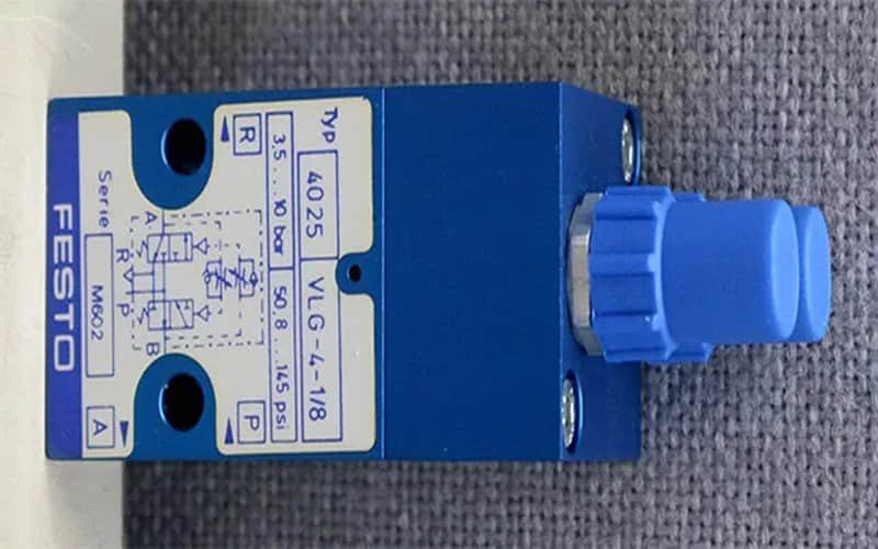
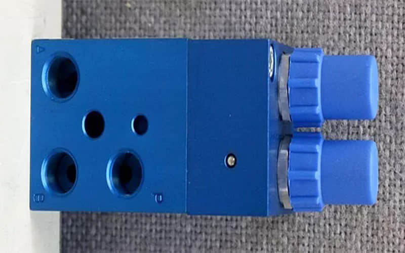
Festo VLG-4-1/8 Type 4025 Pulse Oscillator Datasheet & Quote
Looking for a reliable Festo VLG-4-1/8 Type 4025 pulse oscillator? This technical guide covers pneumatic specifications, logic control roles, adjustable frequency features, and installation instructions.
General Description
The Festo VLG-4-1/8 Pulse Oscillator is an advanced pneumatic device that generates oscillating signals for controlling various actuators and valves in automation systems. Engineered to fit seamlessly into pneumatic logic controllers/elements architecture, its design allows for precise airflow modulation, making it ideal for applications requiring accurate timing, sequential switching, and automated signal processing.
Festo VLG-4-1/8 Type 4025 Technical Specifications
Model: VLG-4-1/8
Flow Rate: 120 to 600 l/min
Operating Pressure: 3 to 8 bar
Frequency Range: 0.5 to 50 Hz
Connection Type: G1/8
Role in Pneumatic Logic Control Systems
Within industrial automation and fluid power circuits, pneumatic logic controllers and associated elements are utilized to execute computational, timing, and switching tasks without relying exclusively on electrical controllers. As a specialized pneumatic logic element, the pulse oscillator converts a steady pneumatic supply into rhythmic, pulsed output signals. This capability is critical for driving reciprocating actuators, managing continuous cycling in assembly lines, and executing automated sequential logic directly within harsh or explosion-prone environments where electrical logic components may face operational limitations.
Festo VLG-4-1/8 Type 4025 Features
Adjustable Frequency Control: Enables fine-tuning of oscillation frequency based on specific system timing requirements.
Compact Design: Space-saving form factor fits easily into tight control cabinets and complex manifold installations.
Reliable Operation: Designed to withstand the rigours of continuous industrial use with stable long-term performance.
Festo VLG-4-1/8 Type 4025 Applications
Automation Systems: Utilized in various automated processes requiring repetitive timing signals and pneumatic sequence control.
Pneumatic Actuation: Ideal for cycling cylinders, vibrating feeders, and air-blast valves in manufacturing setups.
Installation Procedure
Preparation:
Gather necessary tools: wrench, screwdrivers, and appropriate fittings.
Ensure the work area is clean, depressurized, and safe.
Mounting:
Select an appropriate location within the pneumatic control panel or close to the actuator.
Securely mount the oscillator using the designated mounting provisions.
Connecting Air Supply:
Connect the filtered and lubricated compressed air supply line to the G1/8 port on the oscillator.
Ensure all threaded connections are secure and sealed to prevent pressure drops or leaks.
Testing & Commissioning:
Gradually turn on the main air supply and observe the oscillator's cycling function.
Adjust the frequency settings as needed to match the operational parameters of your application.
Final Checks:
Inspect all pneumatic ports and ensure there are no air leaks.
Confirm that the oscillator operates stably within the specified pressure and frequency ranges.
Related Part Numbers
VLG Series Components
Accessories compatible with VLG series oscillators
Need a Quote or Technical Support for VLG-4-1/8?
As an experienced independent supplier of industrial automation and pneumatic components, we provide 100% original, brand-new Festo equipment with reliable quality and fast global shipping from Xiamen, China.
Please check our
Previous: Festo QS-1/4-12-I 190649 Threaded Fast Connector
Back to the top: Festo