
Previous
Next
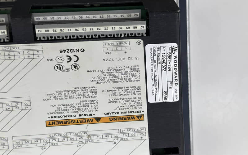
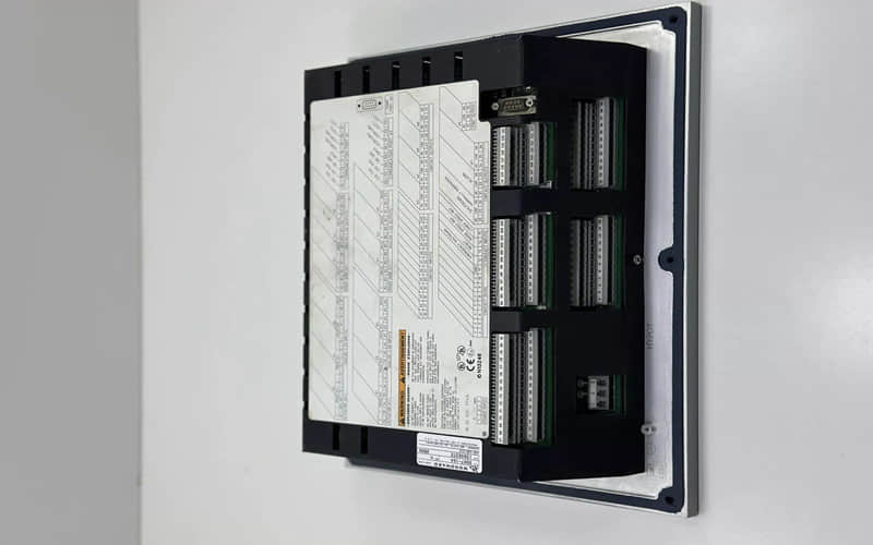
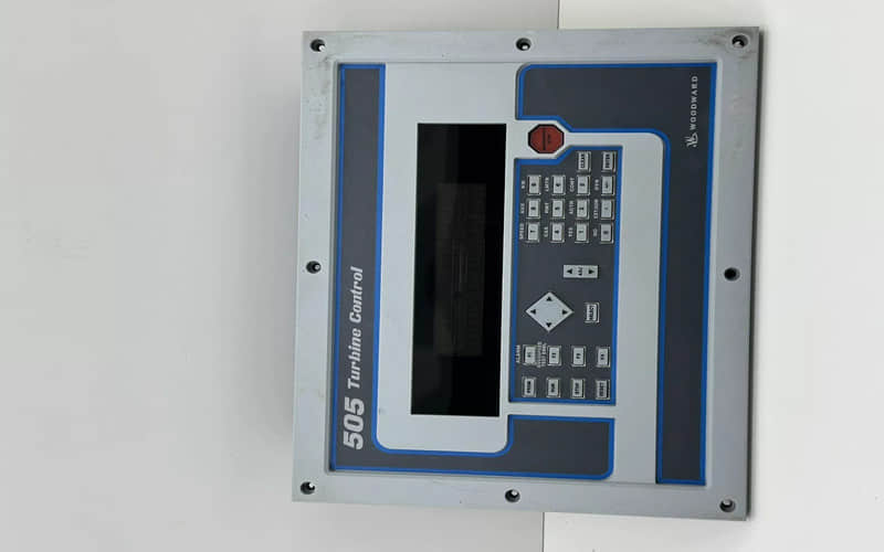
WOODWARD 9907-164 505 Turbine Control
The Woodward 9907-164 is a model number that likely refers to an electronic control module or engine control component commonly used in industrial machinery, turbine systems, or power generation applications. Woodward is known for its advanced control systems and components used to manage and regulate engines, turbines, and other power generation equipment.
一、Woodward 9907-164 Function Description:
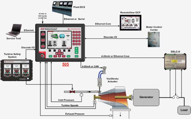
The Woodward 9907-164 is a sophisticated engine or turbine control module designed for use in power generation systems, gas turbines, and reciprocating engines. This module is part of the Woodward Series of Engine Controls and plays a vital role in ensuring the efficient operation and optimal performance of engines and turbines, especially in high-demand or industrial environments.
二、Key Functions:
l Engine and Turbine Control: The primary function of the Woodward 9907-164 is to manage and control the performance of engines or turbines. This includes functions such as:
n Speed regulation to maintain consistent engine or turbine RPM (revolutions per minute)
n Load sharing between multiple engines or turbines to ensure balanced power distribution
n Fuel management to adjust the amount of fuel injected into the engine or turbine based on demand
n Startup and shutdown sequencing for safe and reliable engine or turbine operation
l Advanced Monitoring and Diagnostics: The Woodward 9907-164 features advanced monitoring capabilities, which allow operators to track key performance metrics, such as:
n Engine speed, load, and fuel consumption
n Temperature, pressure, and vibration levels of critical components
n Diagnostic fault codes and system alarms, providing real-time feedback for troubleshooting and maintenance
l Protection and Safety Features: The module is equipped with overload protection and safety shutdown logic that ensures the engine or turbine is safeguarded against potential hazards such as:
n Over-temperature conditions
n Over-speed or under-speed scenarios
n Fuel delivery issues
n Low lubrication pressure When these conditions are detected, the system automatically takes corrective actions, including initiating an emergency shutdown if necessary to prevent damage.
l Communication and Integration: The Woodward 9907-164 can be integrated into larger Distributed Control Systems (DCS) or Supervisory Control and Data Acquisition (SCADA) networks, allowing for remote monitoring and control. It supports standard communication protocols like Modbus, Ethernet/IP, or CAN bus, providing flexibility in various automation systems.
l Customizable Control Logic: The module offers programmable logic capabilities, enabling system integrators to customize control strategies for specific applications. This flexibility allows it to be adapted to a variety of industrial engines and turbines, from small auxiliary power units to large, high-output generators.
l User Interface: A user-friendly interface provides local access for operators to monitor real-time system status, adjust parameters, and configure control settings. The display may include:
n Touchscreen functionality for ease of operation
n Graphical representation of system parameters
n Real-time alerts for system status or faults
三、Woodward 9907-164 Steam Turbines Control Technical Specifications:
l Input Voltage: 24V DC, with over-voltage protection
l Communication Ports: Ethernet, Modbus RTU, CAN bus, and optional serial communication
l Operating Temperature Range: -40°C to +70°C
l Control Range:
l Speed regulation: ±0.5% of the nominal engine or turbine speed
l Load share: Up to 4 units in parallel with load distribution precision
l Inputs:
l Analog: 4–20 mA for temperature, pressure, etc.
l Digital: 8 binary inputs for operational signals
l Outputs:
1. Analog: 4–20 mA for feedback (e.g., engine speed, load)
2. Digital: 8 relay outputs for alarms, shutdown, or control actions
l Power Consumption: 10-15W typical, with energy-saving features
l Dimensions: 280 mm x 180 mm x 120 mm
l Mounting: DIN rail or panel mount
四、Woodward 9907-164 Controller Module Benefits:
ü Reliability: Woodward products are known for their robust design, ensuring consistent operation in demanding environments.
ü Efficiency: Optimizes fuel usage and engine performance, leading to reduced operational costs and improved fuel economy.
ü Safety: Built-in protection mechanisms reduce the risk of engine damage, ensuring the safety of both equipment and personnel.
ü Scalability: The modular design and communication flexibility allow the system to scale and integrate easily with larger control networks.
ü Ease of Use: A highly intuitive user interface and diagnostic features reduce downtime and simplify maintenance.
五、Installation Procedure for Woodward 9907-164
The Woodward 9907-164 is a highly precise engine/turbine control module designed for integration into power generation systems, industrial engines, and turbine systems. Proper installation ensures optimal performance, safety, and longevity of the system. Below is a detailed step-by-step guide for the installation procedure, including associated components and wiring instructions.
Required Tools and Equipment:
l Screwdrivers (Philips and flat-head)
l Torque wrench (for terminal connections)
l Multimeter (for voltage and continuity checks)
l Wire stripper and cutter
l Crimping tool (for terminal connections)
l DIN rail mounting clips (if applicable)
l Thermal paste or heatsink (optional) (if required for heat dissipation)
l Personal protective equipment (PPE) (gloves, safety glasses, etc.)
Step-by-Step Installation Procedure:
1. Pre-Installation Checks:
l Make sure to verify compatibility with your system's architecture before proceeding with installation.
l Verify Power Supply: Ensure that the power supply to the installation site is turned off and that the voltage supply is within the required range for the control module (typically 24V DC).
l Inspect Packaging: Confirm that the Woodward 9907-164 module and associated components have arrived undamaged and are free from defects. Check the part number on the packaging to ensure it matches the part you're installing.
2. Mounting the Woodward 9907-164 Module:
l Location Selection: Choose a dry, cool location that is free from excessive vibrations, dust, or moisture. A DIN rail mount is typically used for this model.
l DIN Rail Mounting:
l Attach the Woodward 9907-164 module to the DIN rail using the provided mounting clips. Slide the module into place and secure it by snapping it onto the rail.
l Use a torque wrench to ensure that any screws used to mount the module are properly tightened (typically 0.5 Nm of torque).
l Panel Mounting: If panel mounting is required, use the Woodward 9907-175 bracket kit to fasten the module to the mounting panel securely.
l Drill the required holes for screws and use the mounting brackets to position the module on the panel.
l Ensure that the module's ventilation slots are unobstructed for optimal cooling.
3. Wiring and Connections:
l Power Wiring:
l The Woodward 9907-164 module operates on 24V DC. Connect the positive terminal (+24V DC) to the +V terminal on the module and the negative terminal (GND) to the -V terminal.
l Use AWG 18-14 gauge wire for power connections, ensuring that all terminals are securely fastened.
l Verify with a multimeter that the voltage is correct before proceeding.
l Input/Output Wiring:
n For analog input signals (e.g., temperature, pressure), connect the 4–20mA signals to the respective analog input terminals.
n For digital inputs (e.g., switches or sensors), connect the wires to the binary input terminals (ensure the polarity is correct).
n For relay output wiring (e.g., shutdown or alarm), connect the output terminals to the relevant control devices (such as alarms, shutdown circuits, or external controllers).
l Communication Wiring:
n For Modbus RTU: Connect the RS-485 terminals to the system's communication bus. Use twisted-pair cables for the best signal integrity.
n For Ethernet/IP: Connect the Ethernet port to your system's Ethernet network.
n For CAN Bus: Use the CAN H and CAN L terminals to connect to the CAN network (if applicable).
l Grounding:
n Ensure that the Woodward 9907-164 is properly grounded to prevent electrical noise and to ensure accurate signal processing.
n Ground the module using the ground terminal located on the module.
4. System Integration:
Connect to External Devices:
l If required, connect the Woodward 9907-164 to external devices such as sensors, actuators, or other control systems.
l Ensure that all wiring conforms to the specifications outlined in the technical manual for proper signal levels and compatibility.
5. Configuration and Calibration:
Once the module is wired, turn on the system power and allow the Woodward 9907-164 to power up.
ü Configure the System:
n Access the user interface (local display or PC-based configuration tool).
n Set up basic parameters such as engine/turbine speed, load sharing, fuel injection limits, and alarm thresholds.
ü Calibrate Inputs and Outputs:
n Perform necessary calibration of sensors connected to the system (e.g., calibrate temperature sensors to ensure accurate readings).
n Check that analog and digital inputs/outputs match expected values and respond to changes.
6. Testing and Validation:
ü Functional Test:
n Simulate normal operational conditions (e.g., startup, shutdown, and load changes) to confirm that the Woodward 9907-164 correctly controls and monitors the engine or turbine.
n Verify that all alarms, shutdowns, and protective actions are properly triggered when required.
ü Communication Test:Test communication with other control systems (e.g., SCADA or DCS) to ensure proper data exchange and control actions.
ü Monitor System Performance:Use the diagnostic display or remote monitoring software to ensure that the system is operating within safe and optimal limits.
7. Finalizing Installation:
ü Secure Wiring: Ensure all wiring is neatly organized and secured to prevent physical damage or interference with moving parts.
ü Labeling: Label all wires and connections for future reference.
ü Documentation: Complete any necessary installation checklists and update system documentation to reflect the installation of the Woodward 9907-164.
ü Post-Installation Maintenance:
n Regular Inspections: Periodically check all wiring and connections for wear, corrosion, or loose connections.
n Software Updates: Ensure that the latest firmware and software updates are applied to the Woodward 9907-164 to maintain compatibility with other systems and enhance functionality.
n Troubleshooting: In the event of faults or alarms, use the diagnostic interface to troubleshoot issues and verify system status.
六、Common Applications:
l Power Generation: The 9907-164 is often used in generator sets and turbine-based power stations for grid support or off-grid systems.
l Marine and Offshore: Used in the control of marine diesel engines and offshore turbines where real-time adjustments and remote monitoring are crucial for uptime.
l Industrial Engines: Found in large-scale pumps, compressors, and fans used in petrochemical, mining, and manufacturing industries.
l Oil & Gas: Employed in oil rigs, drilling rigs, and refineries, where reliable and continuous engine operation is critical.
七.Woodward 9907-164 Related Part Numbers:
l The following are related or compatible parts for the installation and integration of the Woodward 9907-164 control module:
l Woodward 9907-164 Module (Engine/Turbine Control Module)
l Woodward 9907-165 (Auxiliary Module for expanded input/output capabilities)
l Woodward 9907-172 (Communication Interface Module, for Modbus, CAN, or Ethernet integration)
l Woodward 9907-175 (Mounting Bracket Kit for DIN Rail)
l Woodward 9907-188 (Temperature/Pressure Sensor Kit, for feedback inputs)
l Woodward 9910-215 (Ethernet Cable for communication)
l Woodward 9907-240 (Relay Outputs and Protection Kit)
Previous: WAGO 753-514 2-Channel Relay Terminal Output AC 125V DC 30V