1. Introduction: Minimizing Plant Downtime Through Expert Diagnostics
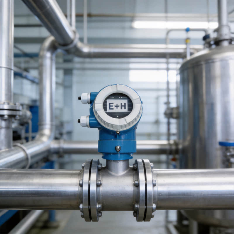
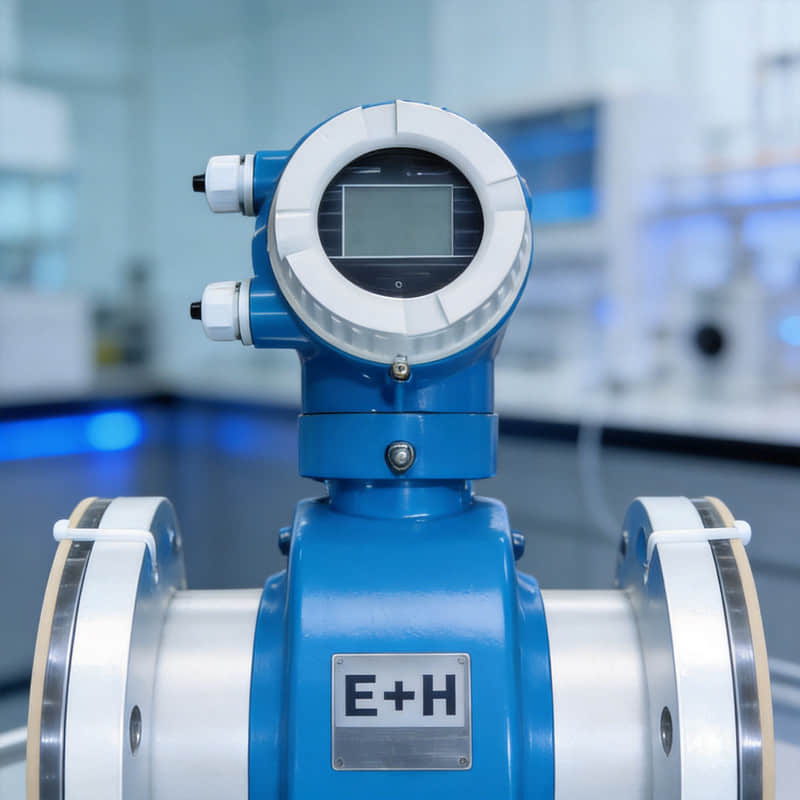
In modern process automation, when an Endress+Hauser (E+H) instrument trips or displays a diagnostic code, every minute of delay translates directly into lost production value and operational risk. Having spent years handling field commissioning and troubleshooting across complex industrial loops, we know that deciphering instrument alarms quickly separates routine maintenance from catastrophic downtime. Whether you are looking for a comprehensive Endress+Hauser troubleshooting guide or trying to decode sudden operational anomalies, mastering device diagnostics is essential.
When addressing E+H device faults, technicians must first separate standardized NAMUR NE 107 status signals—which universally classify events into Failure (F), Function Check (C), Out of Specification (S), and Maintenance Required (M)—from proprietary firmware error codes unique to specific sensor blocks.
To explore matching hardware specifications or source direct replacements during an emergency, refer to our precision-engineered selection of Promass Coriolis Flowmeters and high-accuracy Cerabar Pressure Transmitters.
2. Understanding E+H NAMUR NE 107 Diagnostic Categories
Within the Endress+Hauser intelligent instrument ecosystem, the NAMUR NE 107 status signals E+H framework serves as the core core architecture for diagnostic classification. Issued by the NAMUR user association, this standard categorizes the myriad of proprietary fault codes across different instrument models into four actionable status signals, acting as the "gold standard" for process industry diagnostics.
F (Failure)
Definition: Equipment is damaged, measurement is invalid, and immediate intervention is required.
Application Analysis: This is the most critical diagnostic category, indicating the instrument can no longer provide reliable data. The device may be experiencing hardware failure, sensor damage, or communication loss. For instance, improper installation of an E+H Promag flowmeter (e.g., too close to a pump outlet, inadequate sensor support, stress from poor flange welding, or electromagnetic interference) can cause zero drift and trigger a failure alarm. Furthermore, severe gas entrainment or two-phase flow can completely halt sensor operation.
Troubleshooting: Upon receiving an F-class alarm, immediately dispatch an instrument engineer to the field to check wiring, power supply, and physical sensor status. For E+H devices, utilize Heartbeat Technology's self-diagnostic function, which offers up to 98% test coverage to rapidly isolate the hardware fault.
C (Function Check)
Definition: The device is undergoing routine maintenance or calibration; output signals are temporarily restricted.
Application Analysis: This does not indicate an actual fault. The instrument is simply in simulation, calibration, or maintenance mode. For example, when an E+H flowmeter executes a Heartbeat Verification, the device enters this status. This self-check typically completes in minutes without interrupting the process and can be initiated via the local display, FieldCare, or a web server.
Troubleshooting: Process operators do not need to intervene. However, measurement values may be unreliable during this window and should not be used for critical process control. The device will automatically return to normal measurement mode once the check is complete.
S (Out of Specification)
Definition: Environmental or process conditions are abnormal, potentially affecting measurement accuracy. Process intervention is required.
Application Analysis: Triggered when process parameters (temperature, pressure, flow velocity) exceed the instrument's design limits. For example, process fluid exceeding 120°C requires a specifically rated high-temperature flowmeter. Pushing standard sensors beyond their thermal or pressure thresholds will lead to distorted data and eventual hardware degradation.
Troubleshooting: Operators must adjust process parameters to return the system to the instrument's acceptable operating window. If the process permanently exceeds these limits, the instrument must be replaced with a more suitable model. For example, retrofitting with an E+H Micropilot NMR81 (utilizing 80GHz high-frequency technology and a narrow 3-degree beam angle) is highly effective for bypassing internal tank obstacles in space-constrained applications.
M (Maintenance Required)
Definition: The signal remains valid, but device components are degrading. Scheduled maintenance is necessary.
Application Analysis: This is the cornerstone of predictive maintenance. An M-class alarm indicates a deteriorating trend, such as electrode wear or sensor coating buildup. The monitoring function within E+H Heartbeat Technology continuously tracks conditions like scaling, corrosion, and phase changes. For instance, in industrial scrap metal processing, failing to separate foreign materials from the sensor pipeline can quickly damage the system; the M alarm provides the necessary early warning.
Troubleshooting: Schedule maintenance (e.g., sensor cleaning, electrode replacement) during the next planned plant shutdown. Leveraging continuous self-monitoring reduces the risk of unexpected, catastrophic failures that standard calibration might miss.
The Practical Value of Diagnostic Data Integration
The core value of NAMUR NE 107 lies in simplifying complexity. These four standardized categories allow Asset Management Systems (AMS) to instantly determine "what failed, how severe it is, and whether to send an instrument tech or a process operator."
However, a common field bottleneck is legacy HART gateways. Many older gateways only parse the Primary Variable (PV), dropping advanced diagnostic data (including the NE 107 status bytes). This creates a data disconnect, rendering upper-level AMS blind. To resolve this, modern infrastructure like the HME-685 8-channel HART to Modbus TCP gateway is required to fully support NE 107 standards, seamlessly pipe diagnostic data to the AMS, and transition the plant from reactive firefighting to true predictive maintenance.
3. Top Common Error Codes Across Key E+H Product Lines
While Endress+Hauser offers a vast portfolio, their diagnostic logic remains highly standardized under NE 107. When reviewing general Endress+Hauser error codes, engineers often rely on structured documentation to isolate issues quickly. Below are the most common error codes, root causes, and field solutions across their three primary product lines.
Flow Measurement (Promag & Promass Series)
Typical Codes: S411 (Signal Abnormal) and F261 (Electrode Fault). A detailed Promass flow meter fault guide typically highlights how Coriolis and electromagnetic meters behave under challenging fluid dynamics.
Root Causes: S411 indicates severe signal fluctuation or drift. F261 points to physical electrode issues. Gas entrainment disrupts the induced voltage between electrodes, causing erratic readings. Coating on electrodes creates an insulating layer (common in wastewater or slurry applications), leading to severe signal attenuation.
Field Diagnostics: Perform immediate grounding checks. Ensure equipotential bonding between the sensor and piping, verifying grounding resistance is <1Ω to eliminate common-mode interference. Next, adjust empty pipe detection thresholds or enable low-flow cut-off to prevent false alarms. Check cable shielding on remote-mount installations.
Level Measurement (Micropilot Radar & Liquiphant Series)
Typical Codes: F335 (Echo Loss) and E727 (Tuning Fork Fault).
Root Causes: F335 in radar units is typically caused by low dielectric constant media (e.g., liquid hydrocarbons), foam layers absorbing the microwave signal, heavy condensation on the antenna, or false echoes from tank obstacles. E727 in Liquiphant switches occurs when viscous media or crystallization dampens the fork's vibration, or due to physical mechanical damage.
Field Diagnostics: For radar, optimize threshold configuration to suppress false echoes from internal structures like agitators or heating coils. Utilize signal curve analysis (envelope curves via FieldCare) to visually distinguish the true liquid level from interference. For tuning forks, adjust the sensitivity settings (high/medium/low) to match the specific adhesion characteristics of the fluid.
Pressure & Temperature (Cerabar & TMT Series)
Typical Codes: F140 (Sensor Overload) and S302 (Temperature Limits Breached). Any proper evaluation of a Cerabar pressure transmitter error must check for physical overpressure events.
Root Causes: F140 indicates the pressure cell was subjected to extreme overpressure (e.g., from line purging or water hammer effects), potentially deforming the measuring diaphragm. S302 indicates process or ambient temperatures have exceeded the thermal limits of the sensor or internal electronics.
Field Diagnostics: Access the transmitter's self-diagnostics to check for zero drift. If a permanent plastic deformation of the cell is confirmed, the sensor module must be replaced. Verify the process temperature against the device's thermal rating. In high-temperature applications, install extended diaphragms or cooling fins, or transition to a remote-mount transmitter configuration.
4. Step-by-Step Field Troubleshooting Workflow
Troubleshooting E+H instrumentation requires a systematic, repeatable engineering methodology. Utilizing professional E+H diagnostic codes troubleshooting practices ensures that technicians do not waste time on trial-and-error replacements. The following three-step workflow integrates physical checks, software diagnostics, and repair-or-replace decision matrices to minimize downtime and spare parts costs.
Step 1: Visual & Physical Inspection
Statistically, a significant percentage of instrument faults stem from external environmental factors or installation errors, not the hardware itself.
Wiring integrity: Verify tight connections and look for oxidation on terminals. For remote Promag installations, signal and excitation cable shields must be properly grounded to prevent EMI-induced signal jumping. Ensure IP67 cable glands are fully sealed; moisture ingress due to degraded O-rings is a primary cause of insulation breakdown.
Terminal corrosion: Corrosive plant atmospheres cause copper green or sulfidation on terminals, increasing contact resistance. Clean with electronic contact cleaner and apply conductive paste. Severely oxidized terminal blocks should be entirely replaced, not just sanded down.
Loop power stability (24VDC): Measure voltage across the supply terminals; it must hold between 20.4–27.6 VDC under load. Drops indicate aging power supplies or excessive loop resistance (e.g., from added safety barriers or isolators).
Installation geometry: Confirm the meter is installed in the correct orientation (e.g., full pipe for magmeters) and meets straight-run requirements (typically ≥5D upstream, ≥2D downstream). Check for excessive pipeline vibration, which instantly triggers faults in vortex flowmeters.
Step 2: Diagnostic Software Integration
Once physical variables are eliminated, utilize official E+H DTM-based diagnostic tools like FieldCare and DeviceCare for deep-level parameter analysis.
Device Status Reading: The software translates NE 107 data into intuitive color-coded icons (Red for F, Yellow for M), allowing maintenance teams to instantly prioritize critical loop failures.
Signal Curve Analysis: For Micropilot radar, FieldCare displays the echo envelope curve, instantly revealing if foam or material buildup is masking the true product level. For flowmeters, technicians can monitor excitation current and electrode impedance to detect early-stage sensor coating.
HistoROM Data Logging: Extracts historical operating data, alarm event logs, and parameter changes, helping trace the exact timestamp and process condition that triggered the failure.
Heartbeat Technology: Initiates ISO 9001-compliant metrological verification without process interruption. Highly critical for regulated industries like pharma and F&B.
DTM Library Management: Ensure FieldCare DTMs match the physical device firmware. Outdated DTMs will fail to read modern diagnostic blocks.
Step 3: When to Repair vs. Replace
After isolating the root cause, plant engineers must make a rapid, cost-effective decision.
Field Repairable: Configuration faults (S or C class alarms) are resolved by adjusting parameters (e.g., empty pipe thresholds, false echo suppression) or fixing external wiring/power issues.
Factory Repairable: Damaged sensor modules (electrodes, piezo crystals) or burnt I/O communication boards. E+H factory service includes full post-repair calibration. Replace boards in the field if spares are available; otherwise, send the unit out.
Direct Replacement Required: Permanent mechanical damage (deformed pressure diaphragms, corroded radar antennas, snapped tuning forks) cannot be repaired. Furthermore, if a failing instrument is over 10 years old, upgrading to a modern device with advanced diagnostics offers a lower Total Cost of Ownership (TCO).
Decision Matrix: Compare costs (repair is generally 30–60% of a new unit). Check spare parts availability via the E+H Applicator tool. For custody transfer or safety interlock loops, direct replacement is strongly recommended to guarantee compliance and measurement integrity.
5. Conclusion & Expert Support
When critical process instrumentation triggers unexpected faults, reliable access to expert technical guidance and verified replacement hardware is vital to restoring operations safely. Whether your facility requires diagnostic support for complex loop errors or immediate dispatch of genuine factory-fresh components to eliminate costly delays, our technical team is equipped to assist.
Explore our verified inventory of high-precision Promass Coriolis Flowmeters and reliable Cerabar Pressure Transmitters to secure dependable replacements for your urgent plant maintenance requirements.
Explore More Formats & Join the Discussion:
If you prefer to review this information in alternative formats or want to connect with our engineering community, you can access our resources across multiple platforms:
SlideShare: View and download the structured presentation summary on our Endress+Hauser Error Codes & Troubleshooting Guide
Scribd: Read and share the complete technical document on our Endress+Hauser Field Diagnostics & Troubleshooting Reference Manual
LinkedIn: Join the technical conversation, share your industrial automation experiences, and follow our updates on Endress+Hauser Common Error Codes and Troubleshooting Guide