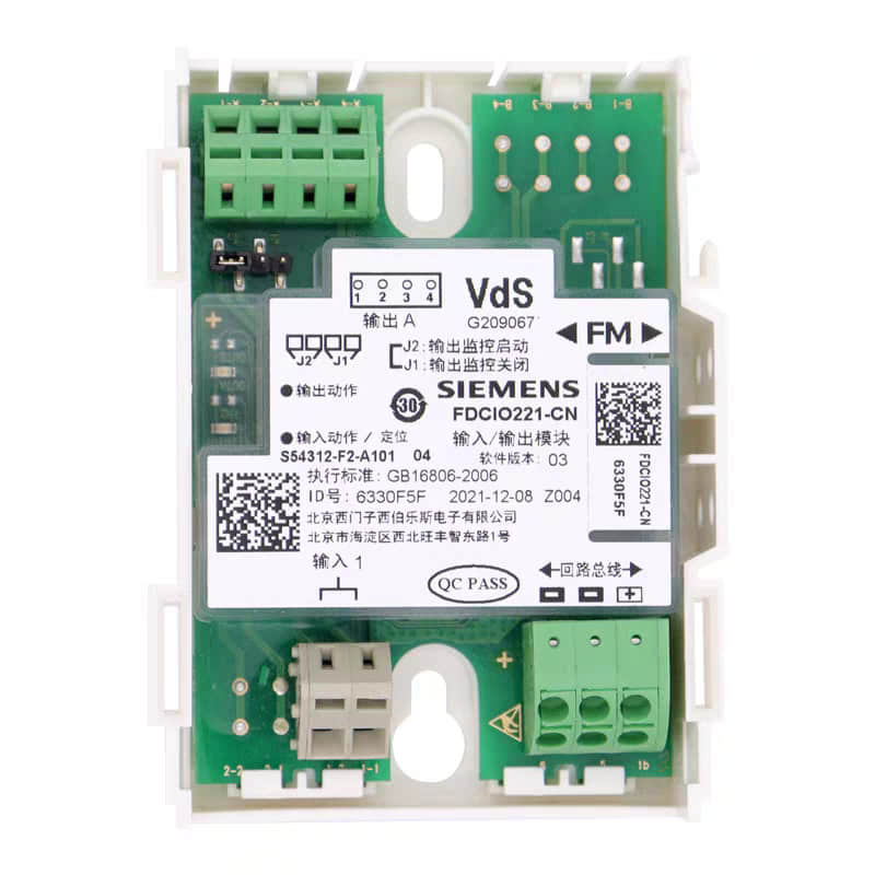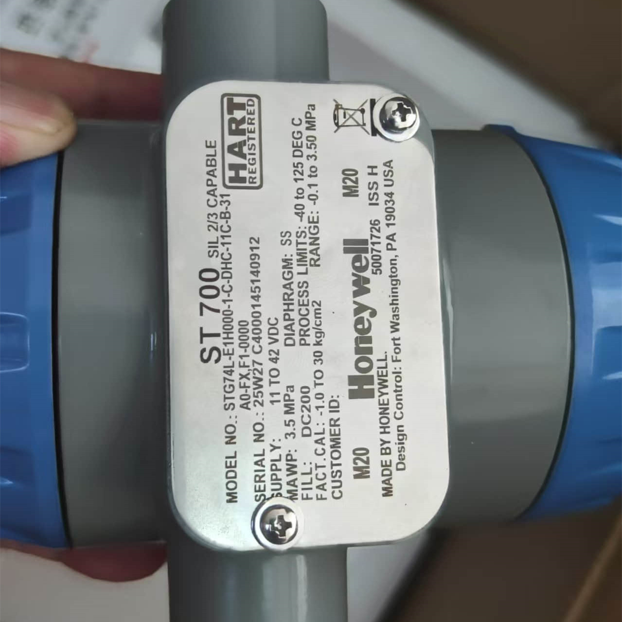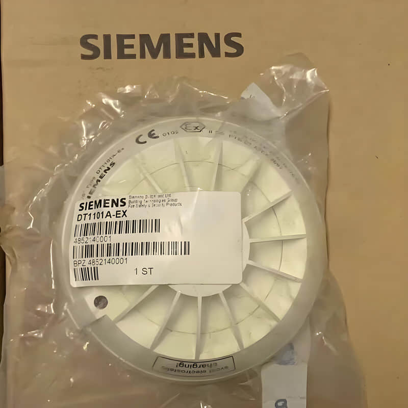
In the daily operation and maintenance of Siemens fire alarm systems, FDCIO221 I/O modules play a key role. They affect how accurate sensor data is in real time. They also affect how quickly and efficiently control commands run.
In complex industrial environments, ensuring the long-term stability of these modules is the cornerstone of effective maintenance. This article covers two main technical bottlenecks during FDCIO221 operation.
They are communication link failures and I/O loop anomalies.
I. In-Depth Examination and Diagnosis of Communication Link Failures
The communication stability of the FDCIO221 module relies on the precise interaction of the bus protocol. In field deployments, frequent module drops or address conflicts are rarely because hardware defects. A challenging link environment usually causes them.
1.1 The Impact of Electromagnetic Compatibility (EMC)
In areas dense with high-voltage industrial equipment, communication buses are highly susceptible to electromagnetic interference (EMI).
If you notice signal distortion or occasional communication dropouts, first check the cable routing.
Make sure the bus cables do not run parallel to the power cables
Optimization Suggestion: Use shielded twisted-pair cables. Keep a reliable ground connection for the shield at the control end. This helps reduce common-mode interference on the FDCIO221 signal transmission.
1.2 Terminal Impedance Matching and Load Balancing
Siemens fire alarm system maintenance have strict requirements for bus loading. Overly long branch lines or mismatched terminal impedance are the primary culprits behind signal reflections.
Technical Reference: When the system reports “Address Conflict,” maintenance staff must check the terminal resistor value.
They must measure it at the end of the line. If the impedance deviates from the standard range, packet loss rates will rise significantly.
Operating Tip: Strictly follow Siemens technical specifications when calculating bus load. Avoid "blindly" adding redundant modules to ensure the bus drive capacity remains within the optimal range.
II. Common FDCIO221 Communication Faults and Systematic Solutions
In Siemens fire alarm systems, like the AlgoRex series, FDCIO221 stability affects sensor data in real time.
It also affects the reliability of fire linkage control. For FDCIO221 communication faults, we recommend a "Software Config → Physical Wiring → Hardware Inspection" diagnostic sequence.
2.1 Software Configuration Mismatch: The Priority
Configuration errors most often cause communication loss. This is common with the FDCIO221-CN model. Its flexible output modes need careful attention
Output Mode Mismatch: FDCIO221 supports both dry-contact and powered outputs. If you set the software file to “Powered Output” and turn on line monitoring, check the hardware jumper.
If you set the hardware jumper to “Dry Contact,” the system will trigger a “Configuration Fault.”
Address Conflicts: For devices communicating via FD18-BUS, unique addressing is mandatory. Duplicate or incorrectly assigned addresses prevent the controller from identifying the node.
Terminal Monitoring Logic: The module’s line monitoring function relies on a 3.3kΩ terminal resistor. Missing resistors or incorrect resistance values will trigger line fault warnings.
Expert Advice: After you change configurations, always use the Cerberus Engineering Tool to download the project file again. This ensures the physical DIP switches or jumpers keep the logical settings synchronized.
2.2 Physical Link Integrity Monitoring
Loop Status: Short or open circuits, including shorts to positive or negative rails, will put the module in protection. This will trigger a controller alarm.
Power Quality: The FDCIO221 operating voltage is 12–32 VDC. If the site's power fluctuates a lot, even a brief drop can restart the module during operation.
This can happen even though the operating current is only 0.85 mA.
Shielding and Grounding: Prevent ground loops caused by dual-end grounding. Ground the shield at only one end.
This helps filter common-mode interference from high-voltage power cables.
2.3 Bus Signal and Hardware Diagnostic Matrix
Symptom | Probable Cause | Action |
Communication Lost
| Loose wiring or reversed polarity | Check terminal connections and cable continuity |
Device Offline
| Duplicate address or incorrect DIP setting | Verify the physical DIP switch against the project file |
Intermittent Error | Signal attenuation or EMI | Check shield integrity and total bus loop length |
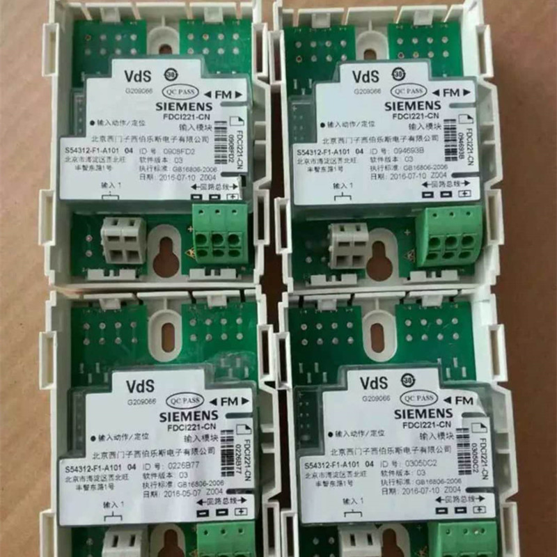
Maintenance Tip: If you think the bus has communication issues, use an oscilloscope.
Monitor the FD18-BUS signal waveform.
This is similar to PROFINET IO troubleshooting. If you have ruled out configuration and wiring, and the module LED is still off or blinking oddly, test a replacement module.
Professional Note: Over many years, I have found the FDCIO221 module needs extra care.
This is true in areas with high electromagnetic interference. To ensure it works perfectly, please pay close attention to your installation setup.
III. FDCIO221 Wiring Guidelines and Deep-Dive Troubleshooting Manual
3.1 Core Technical Specifications
Operating Voltage: 12–32 VDC (outside this range, expect packet loss or logic errors).
Power Consumption: Quiescent 0.32 mA; Operating 0.60 mA.
Output Capacity: Contact rating 2 A @ 24 VDC.
Loop Monitoring: Both input and output loops require a 3.3kΩ terminal resistor.
3.2 Standardized Wiring Practices
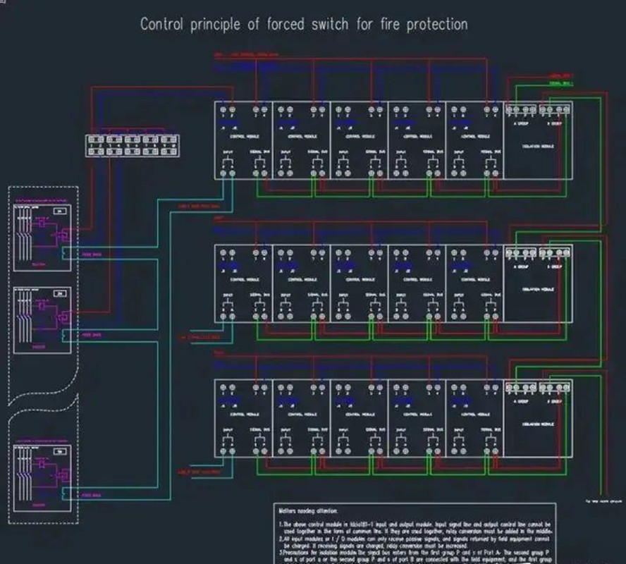
Bus Connection: FDCIO221 uses polarity-insensitive bus technology (D-BUS). Always follow the “single-end shield grounding” rule.
Output Logic Isolation:
Powered Output: Must use a 3.3kΩ resistor to activate loop self-check.
High-Power Control: Given the 2A limit, never drive heavy-duty motors directly. Use intermediate relays for low-voltage isolation.
Inductive Loads: When controlling external relays, always install a 1N5404 flyback diode across the load. This prevents back-EMF from damaging relay contacts.
IV. Specialized EMI Troubleshooting for Complex Industrial Environments
In sites with many VFDs (Variable Frequency Drives) and high-power motors, communication can often drop.
FDCIO221 signal loss troubleshooting
“Ground loops” usually cause this.
“Antenna effects” can also cause them.
Shielding “Zero-Tolerance”: Ground the shield only at the controller cabinet end. If you ground it at both the cabinet and the field end, potential differences will induce interference currents.
Physical Separation: Maintain a distance of ≥ 300mm between communication twisted-pairs and power cables (especially VFD cables). If parallel runs exceed 5 meters, increase separation to over 500mm.
Interference Remediation: If communication failures correlate with equipment operation (e.g., VFD startup), consider installing signal isolators or ferrite beads on the incoming lines. For legacy projects using unshielded cables, upgrading to a professional shielded bus communication cable is the only permanent fix.
V. Operational Experience and Preventive Strategies
5.1 Closing the Loop on "Configuration Consistency"
Do not rely on memory. Sync every site change (module replacement, wiring adjustment) back to the master project file. Always perform a "Hardware vs. Software" verification check before leaving the site.
5.2 System Capacity Management
When using loop cards like the E3M071, strictly adhere to address point limits (e.g., 128 points per loop). Overloading the loop causes not only configuration errors but also insufficient bus power, leading to unpredictable, intermittent drops.
5.3 Maintenance Philosophy: From "Reactive" to "Proactive"
The key to mastering Siemens systems is understanding the design logic. Do not treat alarms as mere noise.
See them as the system saying, "The physical state (resistance, voltage, or signal) has moved past the safety limit." Routine preventive maintenance helps stop failures before they occur.
It includes checking for terminal corrosion.
It also includes measuring bus load voltage.
It also includes cleaning connections.
Why Choose YMZDCS?
We provide high-precision industrial components from Honeywell, Siemens, Emerson, ABB, and Yokogawa.
Why partner with us?
Accuracy: We verify every specification to prevent costly procurement errors.
Reliability: We ensure authentic, high-quality sourcing for your critical systems.
Global Logistics: We handle complex documentation and safe delivery from Xiamen.
Proactive Service: We go beyond sales to support your operational success.
Professional sourcing, simplified.