
Previous
Next
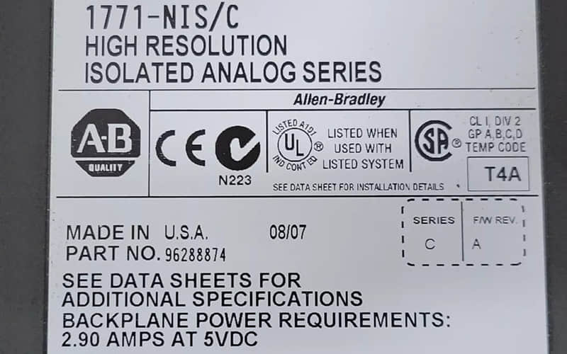
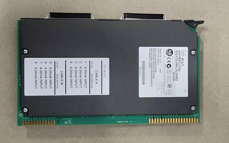
Allen-Bradley 1771-a4b Analog Module
General Description:
The Allen-Bradley 1771-NIS connects various analog sensors and devices, allowing for accurate data acquisition and control in industrial environments.
Technical Specifications of Allen-Bradley 1771-a4b Analog Module:
l Manufacturer: Rockwell Automation
l Brand: Allen-Bradley
l Part Number: 1771-a4b
l Type: Isolated Analog Input Module
l Input Channels: 16 single-ended or eight differential inputs
l Input Ranges: User-selectable (voltage: ±10V, current: 4-20mA)
l Communication Method: Block transfer (BTW and BTR)
l Power Requirements: 750 mA from the backplane
l Operating Temperature Range: 0 to 60 °C
Detailed Features:
1. High Resolution: Provides high-resolution data acquisition for precise measurement of analog signals.
2. Isolated Inputs: Each input is electrically isolated, enhancing safety and reducing interference.
3. Flexible Configuration: Inputs can be configured as either voltage or current, based on application needs.
4. Digital Filtering and Scaling Options: Allows noise reduction and scaling to engineering units for improved accuracy.
Applications of allen bradley 1771-a4b Analog Module :
A. Process Control Systems: Ideal for monitoring temperature, pressure, and flow in manufacturing processes by interfacing with analog sensors.
B. Data Acquisition Systems: Efficiently collect real-time data from multiple sources for analysis and reporting in industrial settings.
C. Industrial Automation Solutions: Integrates seamlessly with other Allen-Bradley components to create comprehensive control systems tailored to specific operational needs.
D. Testing and Measurement Equipment: Used in laboratories and testing facilities to precisely measure physical parameters.
Installation of 1771-a4b Analog Module:
To install the Allen-Bradley 1771-a4b Analog Module:
l Ensure that Power is turned off to avoid electrical shock or damage.
l Insert the module into any available slot in the I/O chassis, aligned with the backplane connector.
l Secure the module using the locking mechanism provided on the chassis.
l Connect wiring to the module’s terminal blocks according to configuration requirements outlined in the user manual.
l Power on the system and verify proper operation through diagnostic indicators.
Related Part Numbers:
l 1771-NBSC
l 1771-NBSE
l 1771-NBSA
Unleashing the Potential of Allen-Bradley 1761
Allen-Bradley 1747-L543 Processor Unit
Exploring the Features of Allen Bradley 1769 CompactLogix
Back to the top: Allen Bradley PLC