1. Introduction
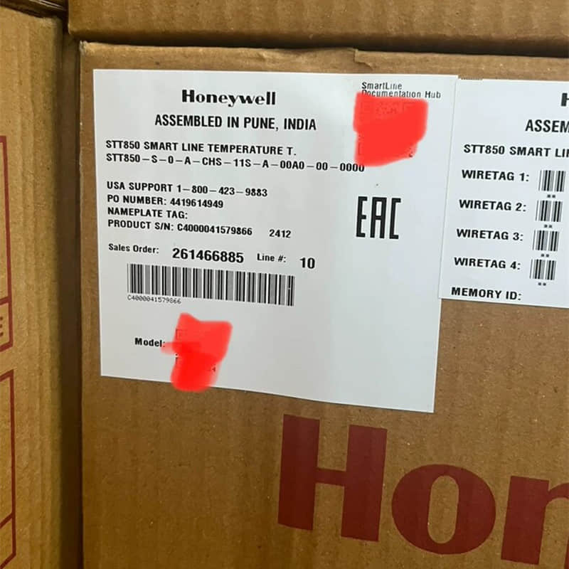
In industrial automation control, hidden errors often surpass overt failures. Taking the widely used Honeywell SmartLine STT850 pressure and differential pressure transmitter as an example. It has strong long-term stability.
It also has a high-precision piezoresistive sensing core.
Even so, it may show zero or span drift after long use in harsh conditions.
This can happen because environmental stress builds up over time.
Supply chain and field engineering work show a clear pattern. A system may often have out-of-spec control loops. It may also trigger false alarms. Or it may lead to batch complaints about pressure tolerances.
In these cases, the cause is rarely a manufacturing defect. Instead, it is the combined impact of environmental stress, installation details, and calibration intervals. Mastering correct root-cause diagnosis and preventive strategies is the key to ensuring stable control loop operation.
For engineers tackling Honeywell STT850 drift troubleshooting, a structured approach is essential to resolving these underlying issues.
2. Core Symptoms: How to Tell if Your Honeywell STT850 Is Experiencing Drift
Identifying sensor drift means spotting a slow, steady, one-way change between the sensor output and the true value. This is not a sudden failure. For high-precision industrial transmitters, like the Honeywell STT850, use these field standards to measure drift.
2.1 Quantifiable Field Criteria for How to Fix Pressure Transmitter Zero Drift
Zero Drift Test: Record the transmitter output when the pipeline is at zero pressure. Ensure the pressure is at atmospheric level. Make sure no media remains in the impulse lines.
4-20mA Analog Output: Standard zero pressure corresponds to 4mA. If the reading stays at 4.02 mA or 3.98 mA for hours, it is slight drift.
If the deviation exceeds 0.08 mA (0.5% of the URL), it needs attention.
HART/PROFINET Digital Variables: Read the pressure directly via a communicator or DCS. The ideal reading at zero pressure is 0. If the reading stays above 0.1 kPa or 0.1% of the URL, it indicates zero drift.
Intervention Threshold: A zero offset exceeding $\pm0.2\%$ of the Upper Range Limit (URL) requires intervention. For example, on an STT850 with a 1MPa range, a zero reading exceeding\pm2 should trigger alertness.
Span Drift Test
In a stable process with constant, known pressure, compare the transmitter reading to a field standard pressure gauge. Use a gauge with higher precision, such as Grade 0.1.
Quantifiable Standard: If the deviation, after excluding the standard gauge’s own error, stays above ±0.5% of full scale. If it also shows a steady increase or decrease, span drift is present.
Time Dimension: Process data using moving average or exponential smoothing methods. If the trendline slope changes by more than $0.01\%$ of full scale per hour, drift is probable.
Long-Term Stability Data Comparison: Honeywell transmitters typically have a nominal long-term stability of $\pm0.1\% \text{ of URL per 10 years}$, referencing standard documentation found in any STT850 pressure transmitter manual & specs. Review calibration records or historical trends from the past 6 to 12 months.
- Judgment method: Compare the actual drift rate to the nominal value.
- If the actual drift rate is much higher than the nominal value, it is abnormal.
- For example, a drift rate of 0.5% of full scale per year is abnormal.
2.2 Distinguishing "Temporary Environmental Thermal Drift" from "Permanent Sensor Element Aging"
This is a key troubleshooting step. It helps you decide whether to adjust the installation environment. Or replace parts listed under Honeywell pressure transmitter replacement parts.
Feature | Temporary Environmental Thermal Drift | Permanent Sensor Element Aging |
Root Cause | Rapid changes in ambient temperature, direct sunlight, startup of heat/cold sources. | Long-term operation, media corrosion, diaphragm fatigue, permanent circuit component parameter changes. |
Change Pattern | Reversible and strongly temperature-dependent. Output signal automatically returns to normal once temperature stabilizes. | Irreversible and continuous. Output shows monotonic increase or decrease, failing to return when temperature normalizes. |
Time Scale | Short-term, fluctuating with temperature over minutes to hours. | Long-term, slowly changing over days, months, or years. |
Impact Scope | Usually affects zero point; minimal impact on span. | May affect both zero and span; span error correlates with input pressure ratio. |
Field Diagnostic Method | 1. Log ambient temperature. 2. Observe if output fluctuation synchronizes with temperature. 3. Recovers automatically within 1-2 hours after temperature stabilizes. | 1. Perform zero/span tests above. 2. Deviation persists without returning. 3. Recurs shortly after calibration. |
Solution | 1. Optimize installation: add sunshades, insulation, move away from heat sources. 2. Adjust damping: increase damping time constant to smooth fluctuations. 3. Software compensation: enable temperature compensation algorithms. | 1. Attempt calibration: perform full calibration; minor aging can be fixed via calibration. 2. Replace sensor: if drift persists or recurs post-calibration, replacement is mandatory. |
3. Root Cause Analyzing: 4 Major Field Culprits Causing Drift
Transmitter drift is not a random glitch, but the result of multiple physical factors working together. You need to understand these root causes before you can prevent sensor drift in industrial transmitters.
Add this step to your maintenance protocol.
① Extreme Thermal Cycling
Mechanism: Temperature variation is the most common cause of sensor drift. Honeywell pressure transmitters comprise various internal materials (metal bases, silicon chips, resistive elements) with differing thermal expansion coefficients. When the process temperature changes fast, these materials expand or shrink at different rates.
This creates internal stress that unbalances the bridge circuit. It can trigger "zero drift." Additionally, temperature alters electronic component resistivity, affecting sensor sensitivity.
Impact on Honeywell Transmitters: The STT850 series uses piezoresistive silicon sensors, where semiconductor materials experience piezoresistive coefficient shifts under thermal influence. Although Honeywell employs proprietary sensor technology (HST) to partially compensate for temperature-induced drift, extreme thermal cycling can push thermal stress beyond compensation limits. Practically, zero-point output may fail to fully return to baseline after temperature stabilization.
Field Diagnosis: Check if the transmitter output changes follow the process temperature curve. If it recovers within one to two hours, it is temporary thermal drift. If it does not recover after the temperature stabilizes, permanent damage may have occurred.
② Long-Term Mechanical Vibration & Shock
Mechanism: Continuous mechanical stress over long-term operation alters the microstructure of internal sensitive elements (strain gauges, piezoelectric crystals). This material-level aging and fatigue is irreversible, gradually degrading physical traits. Excessive installation torque or pipeline vibration also triggers diaphragm deformation.
Impact on Honeywell Transmitters: When installed near pumps, compressors, or large valves, continuous mechanical vibration accelerates internal component fatigue. Despite modular design and rugged housings, long-term vibration can cause elastic creep in the diaphragm. It can also lead to solder joint fatigue on circuit boards. Terminal blocks may also become loose.
Field Diagnosis: If the output changes suddenly during equipment startup or shutdown, suspect vibration-induced drift. If the output rises or falls steadily over operating hours, suspect it too. This should hold even when temperature does not change. Use an oscilloscope to monitor signal lines for regular noise pulses.
③ Overpressure & Line Pressure Effect
Mechanism: Over-range shocks cause elastic element creep. For differential transmitters, line pressure is critical.
If you do not calibrate the line pressure, high pressure on both sides can change properties.
It can affect the isolation diaphragm and the fill fluid.
This can cause zero offsets. Impact on Honeywell Transmitters: Honeywell differential transmitters (like the STD series) must undergo line pressure calibration post-installation. Ignoring this can cause zero offsets exceeding 0.5% of full scale under high-pressure conditions. Furthermore, frequent overpressure shocks accelerate diaphragm fatigue, yielding irreversible zero drift.
Field Diagnosis: After pressurizing the process line, log transmitter output at zero differential pressure. If output deviates from zero as line pressure rises, line pressure compensation is missing. Installing overpressure protection devices effectively restricts pressure spikes.
④ Diaphragm Fouling & Chemical Corrosion
Mechanism: Accumulation of dust, oil, or moisture on sensing surfaces interferes with physical transmission. In chemical or wastewater environments, crystallized media or corrosives alter isolation diaphragm tension, steering output off-target.
Impact on Honeywell Transmitters: Honeywell STT850 units use corrosion-resistant 316L stainless steel or Hastelloy. They also use anti-clogging isolators. However, extreme conditions can still harm them. Risks include media crystallization, long-term acid or alkali erosion, and impulse line blockages.
Field Diagnosis: If output drifts slowly in correlation with media contact time (excluding temperature/vibration), inspect diaphragm surface condition. Back-flush pipelines to diagnose blockages; if you find crystals, soak them in weak acid before you wash.
Comprehensive Preventive Matrix
Culprit | Hardware Protection | Software Compensation | Maintenance Interval |
Thermal Cycling | Install sunshades / insulation jackets | Establish temperature-zero compensation models | Calibrate every 6 months |
Mechanical Vibration | Use shock-absorbing brackets, flexible impulse lines | Increase damping time constant | Check terminal tightness every 3 months |
Overpressure | Install overpressure protection devices | Perform line pressure calibration | Recalibrate after major overhauls |
Diaphragm Corrosion | Select Hastelloy / Tantalum diaphragms | Regular zero/span calibration | Monthly diaphragm visual inspection |
4. Practical Guide: 5-Step Prevention and Calibration Strategy (Tailored for STT850)
For the Honeywell STT850, this five-step strategy is a closed loop.
It covers diagnostics, calibration, installation, and maintenance.
It helps prevent and fix sensor drift.
Step 1: Leverage STT850 Advanced Diagnostics to Catch Anomalies Early
As part of the SmartLine family, the STT850 has built-in self-diagnostics and digital communication. These features form the first line of defense against drift.
Self-Diagnostics: Continuous sensor health monitoring. Via HART or DE protocols, users can remotely read key diagnostic data.
This includes sensor status, early anomaly warnings, and trend logs.
Practical Advice: Utilize the Honeywell Smart Field Communicator (SFC) or DCS system to read STT850 diagnostic data weekly. If "Zero Offset Volume" creeps upward even before reaching alarm limits, schedule maintenance. Trigger calibration when zero offset exceeds 0.1% of full scale rather than waiting for the 0.5\% alarm threshold.
Step 2: Scientific Zero Trim vs. Span Trim (Following a proper Honeywell SmartLine pressure transmitter calibration guide)
Differentiating between Zero Trim and Span Trim during field maintenance is critical; incorrect usage masks true problems.
Zero Trim: Corrects zero offset without altering span slope. Supports direct use with a HART communicator in the field.
Use it when the output differs from 4 mA by a small offset.
The offset must be less than 1% of full scale.
Span Trim: Adjusts sensor sensitivity slope, requiring known standard pressures. You must uninstall the transmitter and send it to a calibration bench.
Core Principle: Technicians can perform Zero Trim on-site; they must do Span Trim on a bench. If identical directional zero drift recurs shortly after Zero Trim, hardware aging or installation issues are present.
Step 3: Installation & Impulse Line Specifications: Cutting Drift Cues at the Physical Layer
Proper installation forms the bedrock of drift prevention, especially addressing thermal cycling, vibration, and overpressure:
Shock-Absorbing Brackets: When installed near pumps, compressors, or large valves, use vibration mounts or flexible impulse lines. These parts keep vibration effects at or below 0.1% FS.
Insulation & Heat Tracing: Install heat-shield covers on transmitter housings to block direct sunlight or radiant heat. Apply electric or steam tracing for low-temperature media.
Condensate Loops (Siphons): Essential for steam or hot media. They use condensate to form a liquid seal. This seal protects diaphragms from direct high heat. Ensure sufficient loop height (ge 300).
Step 4: Calibration Interval Optimization
Calibration frequency should dynamically adjust based on process severity, environmental conditions, and historical data rather than applying a blanket rule.
Baseline Recommendations: For general industrial applications, perform zero calibration every 6 months and full-scale calibration annually. For critical processes, execute zero calibration every 3 months and full-scale every 6 months.
Dynamic Optimization Method: Utilize STT850 historical trend data to build "drift rate" models and optimize maintenance intervals.
Step 5: Comprehensive Preventive Framework
Step | Frequency | Content | Tools / Methods |
Diagnostics | Weekly | Read self-diagnosis status, zero offset trends | HART Communicator or DCS |
Trimming | As needed | Execute Zero Trim (Field only) | HART Command |
Installation Check | Quarterly | Inspect vibration mounts, insulation, condensate loops | Visual check + vibration measurement |
Calibration | 6–12 Months | Full-scale calibration (Bench) | Standard pressure source + calibration software |
Data Analysis | Annually | Evaluate drift rates, optimize calibration intervals | Historical data trends |
5. Conclusion & Sourcing Note
Pressure transmitter drift stems from cumulative multi-source field culprits like thermal cycling, mechanical vibration, overpressure, and chemical corrosion. Effectively controlling drift requires a closed-loop management system spanning "Selection - Installation - Diagnostics - Calibration - Replacement."
Selection is the Foundation: Choosing high-stability sensors is the primary defense line. The Honeywell STT850 series offers a nominal long-term stability reaching pm0.1%, drastically cutting calibration frequency and upkeep costs.
Installation is Key: Correct environments root out drift triggers. Physical shields, insulation, and condensate loops enable early warning and proactive intervention.
Calibration is the Safeguard: Scientific Zero Trim and optimized calibration intervals keep drift within acceptable parameters.
Sourcing Recommendations: Fast Matching of OEM Genuine Parts to Cut Downtime Losses
When sensors suffer severe aging or corrosion unfixable via calibration, prompt component replacement minimizes downtime losses. Sourcing recommendations include:
1. Accurate Model & Specification Matching
Record complete part numbers before procurement. Honeywell naming conventions include series, pressure range, output signal, process connection, and Ex rating. Example: Honeywell STG74S-E2G000-1-A-AHS.
2. Prioritize Genuine OEM Parts
Procure authentic units via Honeywell Authorized Distributors, official OEM channels, or reputable industrial sourcing platforms to avoid unverified aftermarket performance.
3. Spare Part Selection Guide
Application Scenario | Recommended Spare Part Model | Key Characteristics |
General Industrial Process Control | Honeywell STT850 | Long-term stability, HART protocol, IP67 protection |
High-Precision Differential Pressure | Honeywell STG770 | High precision/reliability, tailored for oil, chemical, power sectors |
Severe Conditions (High Temp/Corrosion) | Honeywell 05701-A-0550 | Silicon resonant sensor, 4x overpressure tolerance, fully welded 316L SS diaphragm |
Remote Seal Level Measurement | Honeywell STR82D | Differential pressure, 0.065% precision, explosion-proof certified |
4. Rapid Replacement Workflow
To reduce downtime, stock one or two common models based on past failures.
Use a HART communicator to read the old configuration.
Write it directly to the replacement device.
Run Zero Trim and Span Trim.
Update the asset ledger.
5. Cost-Benefit Analysis
While genuine OEM parts carry higher upfront costs, total lifecycle economics significantly reduce calibration frequency, unplanned downtime, and maintenance labor.
Why partner with YMZDCS?
Accuracy: We verify every spec to prevent costly errors.
Reliability: Authentic, high-quality sourcing for critical systems.
Global Logistics: Safe delivery from Xiamen.
Proactive Service: Technical support that goes beyond sales.
Professional sourcing, simplified.
Explore More Formats & Join the Discussion:
If you prefer to review this information in alternative formats or want to connect with our engineering community, you can access our resources across multiple platforms:
SlideShare: View and download the structured presentation summary on our official Honeywell STT850 Pressure Transmitter Drift & Troubleshooting Guide
Scribd: Read and share the complete technical document on our Honeywell STT850 Transmitter Drift Analysis & Calibration Manual
LinkedIn: Join the technical conversation, share your industrial automation experiences, and follow our updates on Engineering Guide: Honeywell STT850 Pressure Transmitter Drift & Prevention