1. Introduction – The Impact of Loop Faults in Siemens Cerberus Pro Systems
Ask any fire alarm commissioning engineer or system integrator about on-site headaches.
Siemens Cerberus Pro loop fault troubleshooting will almost always top the list. Whether it is an intermittent open-circuit, a hard short, or an elusive ground fault, a loop trouble signal on a Siemens Cerberus Pro system instantly shifts a routine startup into high gear.
In advanced fire alarm systems such as the FC726 and FC723 control panels, the SynoLOOP network must remain reliable. When a fault occurs on the line card—such as the FCL7201-Z3—the panel loses reliable polling with field detectors and input/output modules.
This does more than trigger nuisance alarms or trouble buzzers. It can affect life safety zones. It can leave critical parts of a facility unprotected. This remains true until someone finds and fixes the fault.
Before starting advanced loop card checks on the FCL7201-Z3, you need a clear understanding of the system architecture. You can explore our comprehensive overview in Siemens Fire Alarm Systems: Cerberus PRO, XC10, Controllers & Detectors. In this guide, we explain the main causes of common Cerberus Pro loop signals. We also share a step-by-step diagnostic process to help you clear faults on-site faster.
2. Understanding Siemens Cerberus Pro Loop Architecture (SynoLOOP Technology)
To effectively diagnose loop faults, you must first understand the core of the system—SynoLOOP technology. Using Siemens FCL7201-Z3 line card troubleshooting as an example, it is a key part. It connects and manages the fire detection loops. This card operates under strict technical specifications:
Device Capacity: Supports up to 128 addressable devices per loop.
Transmission Distance: Maximum communication distance reaches up to 2,000 meters.
Topology: Supports both loop and stub line connection methods.
Why Proper Loop Impedance and Shield Grounding Are Critical
The SynoLOOP protocol relies on stable electrical characteristics for communication. If loop impedance is too high because of long cables, thin wires, or oxidized terminals, the signal weakens. This leads to dropped data packets or unpolled devices, triggering intermittent loop fault alarms.
Similarly, proper shield grounding is essential. The shielding layer protects against external electromagnetic interference.
If grounding is poor, such as floating, or incorrect, such as multi-point grounding that creates ground loops, it acts like a giant antenna. It injects noise into the signal lines. This interference corrupts data packets, causes temporary device dropouts, and generates loop fault signals. Maintaining total loop impedance within design specs and following single-point shield grounding ensures long-term system stability.
3. Top 3 Causes of "Loop Fault" Signals on Cerberus PRO Panels
When a panel reports a loop trouble signal, it is vital to find the cause.
Check if it is a Cerberus Pro open-line short circuit or an intermittent ground issue. You can perform preliminary diagnostics by observing the status of the LED indicators on the panel.
1. Open-Line (Broken Wire) Faults
Symptom: One or more devices on the loop go completely offline, and the panel reports missing device addresses.
Primary Causes:
Construction Damage: Cables cut or severely bent by tools like nails or drills during building renovations.
Loose terminals: Installers leave terminal screws loose on field devices (detectors, manual call points). Or there is poor contact between the detector base and head.
Cable Breakage: Cable aging or sustained physical tension causing internal copper snaps.
Diagnostic Method: Use a multimeter to measure total bus resistance. Abnormally high resistance points to an open circuit. Isolate sections sequentially from the control panel outward to narrow down the fault location.
2. Short-Circuit Faults
Symptom: An entire loop or loop branch goes offline, with the panel reporting a short circuit or mass device loss.
Primary Causes:
Detector Water Ingress: Condensation or water leaks inside detectors or bases located in damp environments (basements, kitchens, outdoors).
Insulation Damage: Conduit pulling may strip or pierce cable insulation. This can cause a direct short between positive and negative lines. It can also short a signal to ground.
Component Failure: Internal hardware breakdown within a specific detector or interface module.
Diagnostic Method: Disconnect the loop bus from the panel.
Measure resistance between the positive and negative lines with a multimeter. A resistance reading near zero confirms a short circuit. Use a binary split method or systematically unplug field devices to locate the shorted unit.
3. Ground Faults (Earth Leakage)
Symptom: Intermittent faults during damp weather or changing system loads, with the panel reporting ground faults or insulation warnings.
Primary Causes:
Improper Shield Grounding: This is the most common issue in large retrofit projects. They ground the shield at more than one point. This can create ground loops and electrical noise.
Insulation Degradation: Water can submerge cables, or corrosive environments can damage them. This can reduce insulation resistance and cause leakage current to flow to ground.
Device Moisture: Water ingress causing leakage paths between internal circuits and device housings.
Diagnostic Method: Use an insulation resistance tester (megohmmeter). Measure resistance between the loop bus and ground. Ground can be shielding or chassis. Normal resistance should be above 20OM mega
To fix a Siemens fire alarm loop ground fault, verify shield grounding integrity. Use an insulation resistance tester. This helps remove multi-point ground loops. Low readings require targeted inspections of wet areas, cable splices, and shield grounding terminations.
4. Step-by-Step Troubleshooting Guide for FCL7201-Z3 Line Cards
When a Cerberus PRO panel reports a "loop fault," a systematic diagnostic workflow is essential. For technicians troubleshooting Siemens FCL7201-Z3 line cards, a structured physical-layer check prevents wasted time and repeat alarms. Blindly swapping devices or rewiring runs only wastes time and risks introducing new issues. Here is a three-step diagnostic method for the FCL7201-Z3 line card to help you quickly locate and resolve faults.
Step 1: Isolate the Loop at the FCL7201-Z3 Card and Measure Voltage and Resistance
This is the most fundamental and critical physical-layer diagnostic step. Before diving into software or advanced diagnostics, you must verify the electrical integrity of the loop bus itself.
Isolate the Loop: First, completely disconnect the FCL7201-Z3 loop card from the system by unplugging the loop bus terminal block. This eliminates panel-internal circuit interference and ensures your measurements reflect only field wiring conditions.
Measure Loop Resistance: Use a digital multimeter set to resistance (Ω). Measure the resistance between the loop bus positive (+) and negative (-) terminals.
Normal State: For a full loop, resistance should stay in a reasonable range. Often, it is tens to hundreds of ohms. This varies by length and device count. For a stub line, resistance should match the terminal resistor's nominal rating (usually $120\,\Omega$ under the SynoLOOP protocol).
Open-Circuit Fault: If the multimeter reads “OL” (Over Limit) or a much higher value, there is an open circuit. It may be because of broken cables, loose terminals, or internal device damage.
Short-Circuit Fault: If resistance is near $0\,\Omega$, a short circuit is present.
Stripped insulation, water ingress, or internal component failure usually cause it.
Measure Insulation Resistance to Ground: Switch your multimeter to high-resistance mode or use an insulation resistance tester (megohmmeter). Measure insulation resistance between the loop bus positive (+) and ground (shielding or chassis ground).
Then repeat the test for the negative (−) terminal.
Normal State: Insulation resistance should exceed $20\,\text{M}\Omega$.
Ground Fault: Readings far below spec (e.g., under $1\,\text{M}\Omega$) suggest ground leakage. This can be because of insulation damage, moisture, or poor shield grounding. As noted earlier, incorrect shield grounding is the leading cause of intermittent signal loss in large-scale retrofit projects.
Step 2: Pinpoint Polling Failures Using the FC726 Panel Diagnostic Menu
If tests show no clear open or short circuits, but faults still occur at times, the issue is likely device communication. When you see a persistent Cerberus PRO FC726 fire alarm error, go to the diagnostics menu.
It helps you find the exact device polling failures.
Access the Diagnostic Menu: Use the FC726 interface to open “System Diagnostics” or “Loop Diagnostics.”
These options are usually under Maintenance or Engineer mode, depending on the firmware.
Check Device Polling Status: Select the faulty loop managed by the FCL7201-Z3 card. The panel displays all registered devices and their real-time polling response states.
Identify Faulty Addresses: Locate devices showing "Offline," "Communication Failure," or "No Response." The panel shows specific addresses (for example, address 1.25 for device 25 on loop 1). These addresses match the reported loop fault. This stays within the 128-device SynoLOOP capacity limit.
Analyze Fault Patterns: Determine whether the failure is continuous or intermittent. Frequent communication failures on a physically sound device usually call for base connection checks or unit replacement.
Step 3: Inspect Loop Isolators and Input/Output Modules (e.g., FDCL221)
After identifying specific problem addresses, check associated critical components, especially loop isolators and input/output modules. When tracking an isolated zone failure or an FDCL221 module fault, check field wiring stability. This helps ensure reliable loop communication.
Inspect Loop Isolators: Loop isolators automatically isolate shorted segments to keep the rest of the system running.
Observe LED Indicators: Verify that the status LEDs light or flash at their designated normal frequencies.
Measure Terminal Voltage: Confirm input and output voltages match under normal operating conditions.
Verify Isolation Function: Temporarily bypass suspected faulty isolators under safe conditions to confirm if the fault clears.
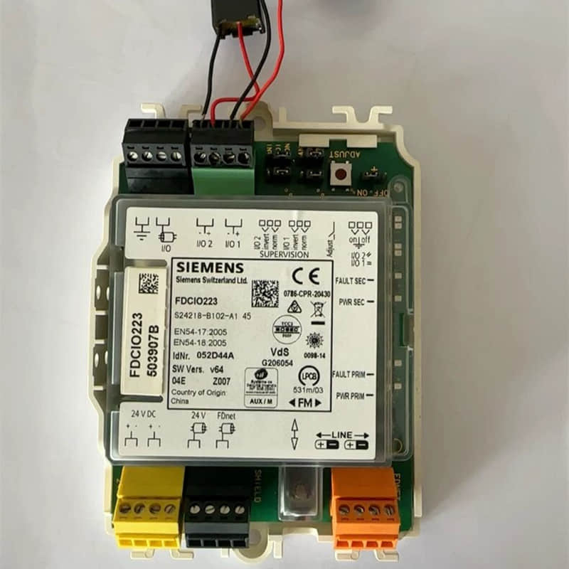
Inspect Input/Output Modules (e.g., FDCIO223): These modules connect conventional detection or control equipment.
Check Module Status: Review input/output channel states through the FC726 diagnostic menu.
Verify external power. Make sure the **24 VDC** external power supply is stable. Voltage drops can cause communication errors.
Check Field Wiring: Inspect termination screws and cable integrity for conventional detectors connected via the SynoLINE.
When you troubleshoot module communication failures on the loop, verify that you wired each interface module correctly. Ensure that each module responds.
For detailed steps to isolate module communication issues, review our guide on Siemens FDCIO221:how to troubleshoot wiring and communication errors. Furthermore, if you manage complex loops with many input devices, read our Siemens FDCIO221: how to solve loop faults in large-scale fire alarm systems.
5. Preventive Maintenance & Best Practices from Field Engineers
"An ounce of prevention is worth a pound of cure," especially in fire alarm system maintenance. Rather than scrambling for emergency repairs after a loop fault occurs, systematic preventive maintenance eliminates vulnerabilities early. Here are key preventive steps from senior field engineers.
These steps can greatly improve the long-term stability of Cerberus PRO systems.
Conduct Regular Loop Integrity Testing
Insulation Resistance Testing: Use an insulation resistance tester (megohmmeter) to measure loop bus insulation against ground. Normal readings must be above $20\,\text{M}\Omega$.
Lower values may mean moisture is getting in. They may also point to bad cable splices or poor shield grounding. As noted earlier, improper shield grounding remains the primary source of intermittent signal loss in large-scale retrofits.
Loop Impedance Testing: Check that loop resistance meets SynoLOOP protocol limits.
These limits allow up to 2,000 meters and 128 devices per loop. Excessive impedance causes signal attenuation and communication failures.
Device Polling Check: Use FC72x panel diagnostic menus, like FC723 or FC726. Run a forced full-loop polling test. The FC723 panel supports modular expansion and can manage up to 12 loops and 756 addressable points. Regular address-by-address polling tests are vital.
Maintain Detailed Loop Topology Documentation
Loop Routing and Paths: Clearly map physical wire routes, cable types, and conduit runs.
Device Inventories and Addresses: Catalog every device type (detectors, manual call points, I/O modules), addresses, and physical locations. Document specific components like Siemens OOH740 detectors or FDM225/FDM226 manual call points.
Isolator Locations: Mark loop isolator placements (such as the FDCL221 Ex Line Adapter). This helps you quickly find fault boundaries during short circuits.
Power Distribution: Record power supply locations and load limits (such as the PSC-12 12 Amp Power Supply). Ensure field loads never exceed rated limits.
Procure Genuine OEM Spare Parts to Avoid Compatibility Risks
Protocol Incompatibility: Proprietary Siemens communication protocols require strict hardware matching; aftermarket parts often fail to parse polling data correctly, causing dropouts or false alarms.
Substandard Performance: Inferior cabling properties fail SynoLOOP specifications, increasing attenuation and bit-error rates.
Safety Hazards: Uncertified power modules can destabilize a 24 VDC output. This can cause interface parts, like the FDCIO223 Transponder, to fail. This may happen during critical fire events.
Cybersecurity Considerations: Official Siemens bulletins note potential vulnerabilities in engineering tools and FC72x panels. Deploying verified OEM components and firmware updates safeguards overall system integrity.
Establish a Fault Logging and Analytical Mechanism
Record every resolved loop fault with structured metadata (symptoms, diagnostic metrics, root causes, corrective actions).
6. Next Steps & Professional Support
Through step-by-step checks and preventive maintenance, you have mastered the key ways to handle "loop faults" in Siemens Cerberus PRO systems. However, during actual operations, you may still face the following challenges:
1. Spare Parts Procurement and Compatibility Risks
Using non-genuine or substandard spare parts is a common cause of recurring system faults. Siemens Cerberus PRO systems use the proprietary C-NET communication protocol.
Non-OEM devices may not read it correctly.
This can cause communication failures or false alarms. To ensure long-term system stability, we strongly recommend:
Procuring Genuine OEM Spare Parts: This includes key parts like the FCL7201-Z3 loop card.
It also includes the FDCL221 Ex Line Adapter loop isolator.
It includes the FDCIO223 Transponder input and output module.
It also includes the OOH740 automatic fire detector.
It includes the FDM225 and FDM226 manual call points.
Power Module Selection: For power supplies like the PSC-12 12 Amp Power Supply, ensure stable output. Make sure the rated load meets system requirements.
Monitoring Product Updates: Siemens often launches new products. One example is the Cerberus PRO FS720 FD30 series. It has FM and UL international certifications.
It uses an industrial Ethernet architecture. It supports networking for up to 200 devices. It also responds to alarms within 0.5 seconds.
2. Cybersecurity and Firmware Updates
Notably, Siemens released security advisories stating that the Cerberus PRO EN engineering tool has vulnerabilities.
These issues also affect FC72x panels, such as the FC723 Fire Control Panel.
Reported vulnerabilities include buffer overflows. Affected products include:
Cerberus PRO EN Engineering Tool: Versions before IP8
Cerberus PRO EN Fire Panel FC72x: Versions before IP8
Successful exploitation of these vulnerabilities could allow unauthenticated attackers to execute arbitrary code or create denial-of-service conditions on affected products. Therefore, regularly checking and applying official security updates is critical.
3. Professional Technical Support
When encountering complex faults or requiring system upgrades and retrofits, our technical team provides:
Customized Procurement Solutions: Offering optimal spare parts lists and replacement options based on your system configuration and project requirements.
Remote Diagnostic Support: Assisting you in analyzing fault logs and localizing difficult problems.
On-Site Technical Services: Providing full-process support from scheme design to construction acceptance for large-scale retrofit projects.
7. Why Choose YMZDCS?
We provide high-precision industrial components from Honeywell, Siemens, Emerson, ABB, and Yokogawa.
Why partner with us?
Accuracy: We verify every specification to prevent costly procurement errors.
Reliability: We ensure authentic, high-quality sourcing for your critical systems.
Global Logistics: We handle complex documentation and safe delivery from Xiamen.
Proactive Service: We go beyond sales to support your operational success.
Professional sourcing, simplified.
8. Extended Reading & Resource Downloads:
To make it easier to review and share, we synced the key technical documents. We also uploaded the full guide to major professional platforms:
�� Read Online (Detailed Version): View the complete high-definition PDF file on our Scribd: Siemens Cerberus Pro Loop Fault Troubleshooting & Diagnostic Manual
�� SlideShare Presentation: Browse the related graphical presentations on our SlideShare: Siemens Cerberus Pro Loop Fault Troubleshooting Guide
�� Industry Discussion & Networking: Check out peer discussions on our LinkedIn Article & Network Update: Siemens Cerberus Pro Loop Fault Troubleshooting: Field Guide