1. Executive Summary & Why Proper Replacement Matters
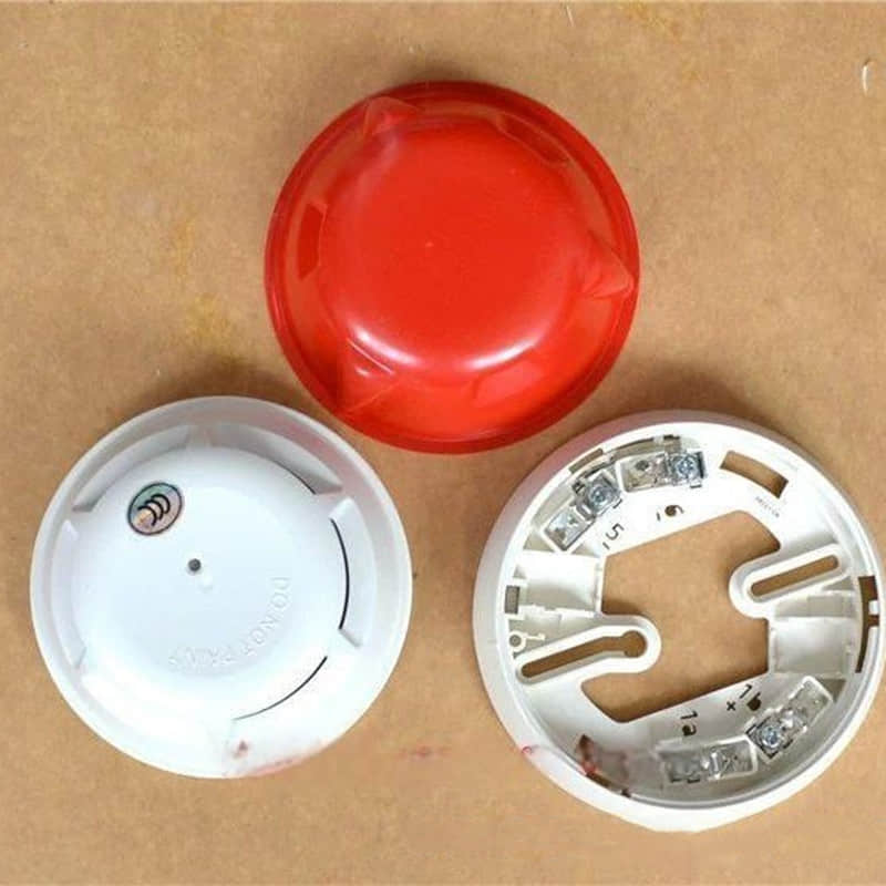
In modern commercial and industrial fire safety architecture, the reliability of your detection network is non-negotiable. Siemens Cerberus Pro detector troubleshooting systems use industry-standard intelligent devices, like the OP921 smoke detector.
Together with the matching DB721-CN base, they support early-warning life safety infrastructure. However, years of operational exposure to dust, thermal fluctuations, and environmental aging inevitably lead to sensor degradation, creeping calibration drift, or intermittent false alarms.
When a detector reaches this threshold, prompt and precise replacement is critical. Beyond silencing a nuisance alarm, a strict replacement protocol helps meet local fire codes.
It also protects facility compliance and ensures continuous life safety for building occupants.
Drawing from years of hands-on field engineering and maintenance work in large commercial facilities, one issue stands out. The hidden danger lies in unverified or improper component replacement.
Many maintenance teams treat detector replacement as a simple "plug-and-play" task. They may overlook key factors like device bus addresses, base contact condition, and loop current settings. Improperly seated devices, wrong terminal torque, or mismatched firmware can cause serious issues.
These issues often include system communication errors and loop faults (Siemens fire alarm loop fault repair). These faults can isolate entire detection zones, leaving segments of a facility completely blind.
Mastering the correct replacement procedure for core units such as the OP921 and DB721 reduces risk. It preserves loop integrity and ensures your fire alarm system performs when it matters most.
2. Siemens DB721 Base Wiring and Installation, Pre-Replacement Checklist & Safety Protocols
Proper preparation before replacing a Siemens fire detector is critical for safety and to prevent false alarms.
System Isolation & Control Room Coordination
Before any physical removal, notify the fire alarm control panel (FACP) operator.
Ask them to place the related loop in test or maintenance mode.
Preventing False Alarms: Disconnecting a live detector without isolation will trigger an open-circuit fault on the loop. This can unintentionally activate facility-wide notification appliances, smoke extraction fans, and fire shutters.
Protocol: Always ensure the control room places the zone on "bypass" or "test" status before proceeding.
Electrical Safety & Preparation
Loop Voltage Verification: Use a digital multimeter to measure the total bus voltage. Confirm it is within the normal operating range, about 24 VDC. Although loop-powered devices operate at low voltage, avoiding live-circuit shorting protects the panel interface.
ESD Protection: Wear an anti-static wrist strap to protect sensitive internal microprocessors from electrostatic discharge, particularly in low-humidity environments.
Personal Protection: Use protective eyewear and gloves to shield against accumulated dust, ceiling debris, or insulation fibers during removal.
Spare Part Verification & Compatibility
Always verify that replacement components match the existing system architecture:
Siemens OP921 Optical Smoke Detector: Designed for commercial offices, hotels, and general spaces with rapid-response photoelectric sensing. Per manufacturer guidelines, avoid installing units before construction cleanup finishes to prevent dust or moisture contamination.
Siemens HI921 Heat Detector (as applicable): Use this detector in areas with lots of smoke or dust.
Standard optical detectors may cause false alarms in these areas.
Siemens DB721-CN Detector Base: Made from flame-retardant ABS and rated IP30, this base supports mounting.
It also provides secure data transmission through internal metal spring contacts.
Base Compatibility Warning: Do not mix legacy bases with newer series heads. Although the older DB720-CN and newer DB721-CN bases look similar, small pin and latch changes can cause loose connections. These issues may lead to dropped signals or physical damage.
Tool Readiness Checklist
Tool | Purpose |
Specialized Removal Tool | Unlocks proprietary locking tabs on Siemens detectors (such as the FDFT291 tool) without damaging the housing. |
Digital Multimeter | Measures loop voltage and verifies line continuity at the base terminals. |
Anti-Static Wrist Strap | Prevents electrostatic damage to internal detector circuit boards. |
Precision Flathead Screwdriver | Secures terminal screws when tightening wiring inside the mounting base. |
Label Marker & Tape | Records loop IDs and address settings for accurate system mapping. |
Compressed Air / Clean Cloth | Clears out accumulated dust and debris inside the base prior to mounting the new unit. |
Engineering Considerations & Address Configuration
Addressing Validation: Siemens intelligent devices rely on precise hardware or software addresses. Record the address of the failing unit. Set up the replacement detector the same way. This lets the FACP recognize it at once.
Environmental Placement: Keep the replacement location away from HVAC supply vents or windy doorways. These can blow dust into the sensor chamber and cause false alarms.
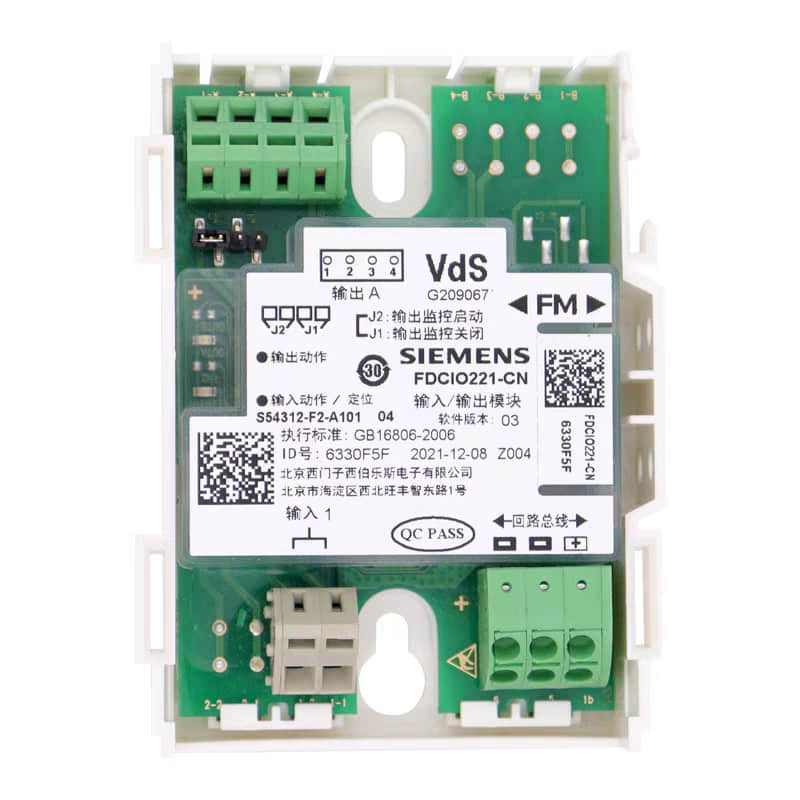
3. Step-by-Step siemens op921 replacement guide procedure
The following workflow for replacing Siemens fire detectors follows official technical specifications. It covers the full process, from removing the old device to installing and testing the replacement.
Step 1: Removing the Faulty Detector
Specialized Tooling: Insert a dedicated removal tool, such as the FDFT291, into the side slots. Rotate it counterclockwise 15 to 30 degrees until you hear a click. This click releases the locking mechanism. Warning: Forced manual rotation can shear the base latch structures.
Extraction: Gently pull the detector straight down. Do not tension or pull the loop wiring connected to the base terminals.
Base Contact Inspection: Use a bright flashlight to check the internal metal spring clips. Check the positive, negative, and data contacts for oxidation, corrosion, or bending.
Siemens DB721-CN bases use flame-retardant ABS housing. If you see green copper patina on contacts, clean them carefully. Use fine abrasive paper or a specialized contact cleaner.
Data Logging: Take a photo of the DIP switch address settings on the hardware. Or record the software address label from the removed unit. This helps you set up the replacement correctly.
Safety Precondition: Confirm the fire alarm control panel (FACP) puts the loop into test or maintenance mode.
Do this before any physical removal.
This helps prevent open-circuit loop alarms.
Step 2: Inspecting the Base and Wiring
Inspection Item | Operational Requirement | Common Issues & Symptoms |
Dust & Debris | Clear internal accumulation using compressed air or a soft bristle brush. | Heavy buildup causes intermittent contact resistance or detector ground faults. |
Contact Corrosion | Check metal spring clips for oxide layers; treat with electrical contact cleaner if necessary. | Humid operational environments accelerate copper oxidation and signal loss. |
Terminal Security | Lightly nudge terminal screws with a precision flathead screwdriver to verify conductor tightness. | Thermal cycling and mechanical vibration loosen wire terminations over time. |
Housing Integrity | Visually inspect the molded base for stress fractures, cracks, or thermal warping. | Overtightened mounting screws or impact damage compromise structural seating. |
Loop Voltage | Measure terminal potential using a digital multimeter (nominal operating range: DC 18–28V). | Voltage drops indicate downstream bus resistance or power supply degradation. |
Base Compatibility Note: Siemens makes the DB721-CN base for the FC720 system series. It works with OP921 photoelectric smoke detectors and HI921 heat detectors.
Although DB720-CN legacy bases look like older bases, there are small differences in the terminal interface size.
Do not mix deployments. Reuse existing bases only if structural inspection is pristine; otherwise, replace them to eliminate loop communication dropouts.
Step 3: Address Configuration
Siemens S-LINE series detectors support two configuration methods depending on system architecture:
Method A: Hardware DIP Switch Addressing (Legacy Systems)
The rear housing features an 8-bit DIP switch array utilizing binary encoding (valid address range: 1–127).
Procedure: Use a precision micro-screwdriver to mirror the exact ON/OFF switch positions of the removed unit.
Caution: Always de-energize the loop before adjusting DIP configurations to protect internal logic circuits.
Method B: Software Auto-Addressing (Recommended for Modern Loops)
Advanced ASA-technology loops (such as Cerberus PRO architecture) support automatic device enumeration.
Procedure:
Lock the new detector securely into the mounting base.
Access the FACP management interface and initiate an "Auto-Enrollment" or "Device Scan" routine.
The system automatically registers the device ID and maps its physical address without manual intervention
Advantage: Eliminates configuration errors during large-scale retrofits.
Step 4: Installing the New Unit
Alignment: Line up the three positioning guides on the replacement detector (such as the Siemens OP921). Match them to the slots on the mounting base. The non-reversible alignment geometry prevents incorrect insertion.
Locking: Push the unit upward into the base. Rotate it clockwise 15 to 30 degrees. Stop when you feel a firm click. This confirms that the lock secures the unit.
LED Status Check: After you seat the unit, the on-board LED should pulse once to confirm that power started. It then enters normal polling mode and flashes every 5 to 10 seconds.
Functional Testing:
Apply a test magnet or optical filter tool (such as the FDLU242). This simulates combustion particles and confirms the panel alarm annunciation.
Confirm that the FACP correctly displays the device address and active alarm state.
Placement Guidelines: Keep at least 6 inches (15 cm) of clearance from side walls. Place units 12 inches below ceiling-wall corners. Avoid direct installation near HVAC supply diffusers to prevent false triggers from high-velocity air streams.
Post-Verification Procedures
System Restoration: Contact the control room operator to exit test mode and restore standard automated network supervision.
Burn-in Monitoring: Review event logs over the next 24 hours. Confirm there are no intermittent trouble signals or nuisance environmental trips.
Documentation: Archive the replacement date, device part numbers, address assignments, and test verification logs in the facility maintenance registry.
4. Post-Replacement Testing & Verification
Following detector replacement, you must test and verify the system to ensure proper operation.
This confirms stable loop communication and accurate alarm transmission to the fire control room. The standardized acceptance workflow is detailed below.
Loop Communication Status Check
Execute the following verification steps on the Fire Alarm Control Panel (FACP):
Panel Status Observation: Confirm that the panel displays no "Communication Fault" or "Trouble" errors. If fault alarms appear, potential root causes include device address conflicts, base contact misalignment, or abnormal loop voltage.
Simplified and split version
Device Registration is needed for auto-addressing systems.
Examples include the Cerberus PRO series.
Run an Auto-Enrollment or Device Scan on the panel. This helps ensure the panel correctly identifies the new detector. Once installed, the Siemens OP921 detector LED should pulse every 5 to 10 seconds. This indicates normal supervisory polling status.
Loop Voltage Inspection: Use a digital multimeter to measure voltage between the base terminals. The normal operating range is DC 18V to 28V. If voltage levels are irregular, inspect the loop power supply modules.
Field Trigger Testing (Functional Testing)
Deploy professional test equipment to simulate combustion signatures and verify detector responsiveness:
Test Type | Tools & Methodology | Expected Result |
Smoke Test | Apply aerosol test gas or a test magnet (such as the FDLU242 testing tool) to simulate particulate presence. | The detector LED should transition to steady illumination (alarm state), and the FACP must display the corresponding address alarm signal. |
Thermal Test | Apply a controlled heat gun or dedicated thermal tool (keeping temperature within rated device limits). | The detector should trigger an alarm condition within specified thermal thresholds. |
Interlock Test | Trigger the alarm and monitor whether notification appliances, smoke extraction fans, and fire shutters respond per preconfigured logic. | Associated fire safety interlocks must activate within regulatory timeframes. |
⚠️ Important Note: Per NFPA 72 standards, you must conduct mandatory functional testing on all newly installed detectors. Always notify the control room to switch the system into "test" mode beforehand to prevent unintended facility evacuations.
Alarm Signal Transmission Verification
Control Room Confirmation: When a local detector triggers, the FACP must instantly show the alarm address. It must also show the detector type (smoke or heat) and the time.
Siemens fire alarm systems use a distributed smart design. Detectors process signals locally. They then send them through the loop bus to the control panel.
Signal Latency Assessment: Measure the time between the field trigger and panel annunciation. Standard latency should stay under 2 seconds. Excessive delays require inspecting loop capacitance loading or protocol settings.
- Remote notification check: See if the system connects to an off-site monitoring center or a city fire network.
- Confirm that events upload successfully.
Acceptance Logging & Documentation
Upon completing all verification procedures, record the following parameters in the facility maintenance log:
Replacement date and technician sign-off.
Replacement part numbers, including the Siemens OP921 detector and Siemens DB721-CN base.
Device address assignment (hardware DIP configuration or software-mapped ID).
Test results (pass/fail status) along with any remediation notes.
FACP event confirmation screenshots or print logs.
Troubleshooting Quick Reference
Fault Symptom | Probable Cause | Corrective Action |
Panel Displays "Trouble" | Detector not securely locked, address conflict. | Reseat the detector housing, verify address configuration. |
Detector Unlit | Base contact resistance, zero loop voltage. | Inspect internal base spring clips, measure loop voltage. |
Alarm Not Transmitted | Protocol mismatch, bus wiring fault. | Check bus terminal wiring, verify panel device mapping. |
5. Common Pitfalls & Troubleshooting Tips
Even when following standard procedures, technicians may occasionally encounter operational issues during the replacement of Siemens OP921 smoke detectors and DB721-CN bases. Real field engineering experience forms the basis of the following troubleshooting guide. It helps you quickly diagnose and fix common issues.
1. Address Conflicts and Unrecognized New Devices
This is the most common issue after replacement. It usually shows as a “Communication Fault” or “Trouble” message on the FACP. This means the network loop does not recognize the new device.
Address Verification & Consistency:
For legacy systems with DIP switch addressing, the new detector’s 8-bit switch array must match the removed unit.
Set the binary switches to the same address as before.
Valid addresses range from 1 to 127. Recommendation: Always photograph the original DIP switch positions before unmounting the old unit.
For modern auto-addressing systems, like the Cerberus PRO series, start Auto-Enrollment from the FACP.
You can also start a Device Scan from the FACP. Once initialized, the Siemens OP921 detector LED will pulse every 5 to 10 seconds. This shows normal supervisory polling status. An unlit LED confirms it has not registered.
Base Contact & Loop Voltage Diagnostics:
Use a digital multimeter to measure the terminal voltage across the mounting base. The normal range is 18 to 28V DC. Irregular voltages require inspecting loop power supply modules and total bus wiring integrity.
Inspect the metal spring clips inside the Siemens DB721-CN flame-retardant ABS base for oxidation, corrosion, or distortion. If you see green copper patina, clean the contacts well. Use fine abrasive paper or an electrical contact cleaner.
Duplicate Address Resolution:
If an identical address already exists elsewhere on the loop, the new device will fail to enumerate. Review the active device register on the FACP to ensure address uniqueness.
For large, multi-loop installations, use a dedicated handheld programmer, such as Siemens tools. Verify and assign detector addresses before mounting.
Base Compatibility Check
Avoid mixing legacy bases with newer device heads. Although older DB720-CN and newer DB721-CN bases look similar, small terminal interface differences can cause loose connections. These issues may trigger intermittent fault codes or fully disrupt the loop. Always utilize official matching components.
2. Environmental Nuisance Alarms Caused by Excessive Dust and Debris
While the Siemens OP921 photoelectric smoke detector offers high sensitivity to combustion particles, deployment in environments prone to heavy dust, steam, or high humidity can lead to premature false alarms.
Nuisance Alarm Source | Operational Characteristic | Preventive & Remedial Solutions |
Construction Dust | Frequent false trips during active building fit-outs or remodeling. | Keep detectors uninstalled until construction cleanup is completely finished, or utilize protective dust covers during active work. |
HVAC Airflow Proximity | Spurious alarms triggered specifically when ventilation systems cycle on. | Relocate or space detectors away from direct HVAC supply diffusers, high-velocity air streams, and open entryways. |
High Humidity & Condensation | Periodic nuisance alerts during humid weather or seasonal temperature swings. | Avoid installing standard optical units in high-moisture zones (such as near industrial washdowns or kitchens); deploy multi-criteria detectors (such as the OOH740) for harsh environments. |
Accumulated Particulates | Gradual increase in false trip frequency over extended operational cycles. | Execute routine preventive maintenance by cleaning internal optical chambers with compressed air or soft brushes at least semi-annually. |
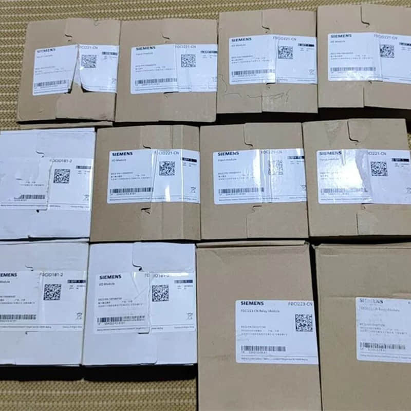
6. Sourcing and buying genuine Siemens fire alarm parts
To ensure long-term system stability, regulatory compliance, and full compatibility, facility managers and contractors should buy verified OEM parts.
When replacing a Siemens fire detector, use genuine parts to ensure smooth integration with Cerberus Pro loops.
This also avoids hidden risks linked to unverified gray-market alternatives.
Complete Product Availability: From OP921 smoke detectors and DB721-CN bases to specialized modules and control panels, maintaining a ready inventory minimizes facility downtime.
Global B2B Supply Chain Support: Streamlined logistics ensure rapid delivery for urgent retrofits and scheduled maintenance overhauls.
For project technical documents, bulk quotes, or help with complex system upgrades, contact our engineering support team.
They can source genuine Siemens fire alarm parts directly for your facility.
Why Choose YMZDCS?
We provide high-precision industrial components from Honeywell, Siemens, Emerson, ABB, and Yokogawa.
Why partner with us?
Accuracy: We verify every specification to prevent costly procurement errors.
Reliability: We ensure authentic, high-quality sourcing for your critical systems.
Global Logistics: We handle complex documentation and safe delivery from Xiamen.
Proactive Service: We go beyond sales to support your operational success.
Professional sourcing, simplified.
Explore More Resources:
View the presentation slides on slideshare: Siemens Fire Detector Replacement & Maintenance Guide
Access the technical document on Scribd: Technical Manual: Siemens Fire Detector Replacement and Loop Troubleshooting
Connect with us on LinkedinL: Field Guide: Siemens Fire Detector Replacement & Maintenance