
As an old-fashioned automation control system, the Siemens FS18 system is renowned for its reliability and stability. But every system will experience a variety of issues during long-term operation. This chapter focuses on the most frequent FS18 mainframe problems and solutions. The goal is to provide technicians and engineers with a practical troubleshooting manual on the Siemens Fire alarm systems.
This chapter has two parts:
l The first half focuses on analyzing equipment. Which is a key aspect to know the stability of the whole operation.
l The second half compiles individual, rare cases encountered over many years of practical experience. While these experiences are not frequent, they provide unique insights and references for diagnosing complex situations.
We hope this collection will serve as a valuable reference for you, helping you quickly resolve field issues.
1. General Failures of Front-End Equipment and Problem-Solved Solutions:
1.1 Communication Failures:
During on-site commissioning, first confirm that the device ID matches the software record. If you find any discrepancies, immediately correct them within the software.
If the device still has no voltage, first check that you have tightened the base and disconnected the loop wires. Next, check the bus for strong interference sources like high-power motors and inverters. Route strong and weak wires to different slots.
If you still don’t know the location of the problem, replace the suspected part with a working device. This will help you quickly determine whether the device or wiring causes the problem.
Finally, use a multimeter to measure the loop voltage and impedance and compare them with normal values. If the resistance seems unusual, check for minor oxidation on the connector or grounding.
1.2. Module Open Circuit:
The normal no-load voltage at the FS18 series bus end is DC 24 V. Even under load, it should still be ≥ 15 V
If you see the message “3.3 kΩ feedback resistor not detected,” check the following. First, connect a 3.3 kΩ ±5% resistor to the feedback terminal of the input/output module. Also, look for any loose solder joints. Then, measure the voltage at the terminal.
If it is < 15 V, it indicates an open circuit or severe contact failure. Begin at the fire alarm controller. Check each box for loose terminals.
Pay special attention to areas that have recently improved or see a lot of traffic. Focus on areas where cables are likely to break more frequently.
1.3 Illegal Module Parameters:
Causes: This issue is usually caused by a mismatch between software configuration and hardware settings. This can happen in two ways.
First, the jumper cap on the module output terminal may not match the output type set in the program. If the jumper is J1, change the program for dry contact (passive) mode. If the jumper is in J2, set the program to active mode.
You must select the wiring methods for these two modes based on actual needs, as they differ completely. The software model of the module does not match the actual module on-site.
Solution: First, check the module model and jumper cap positions on-site. Modify the module model and output type settings within the programming environment. Download the program to your host computer.
1.4 Type Mismatch:
The device type in the program must exactly match the actual device on-site. Otherwise, a “Type Mismatch” error will occur.
This usually happens when someone picks the wrong model during software setup. It may also be that the installed device does not match the design sketches. When you use an 18S host system, it is crucial to differentiate between new and old kinds of devices. If you select the wrong one, it could result in an error and give you false alarm messages.
The solution is simple. First, check the specific module model on-site. Then, choose the correct model in the programming software.
After correcting the device type, re-download the program. Check that the version of the software matches the hardware. Install the device according to the model list.
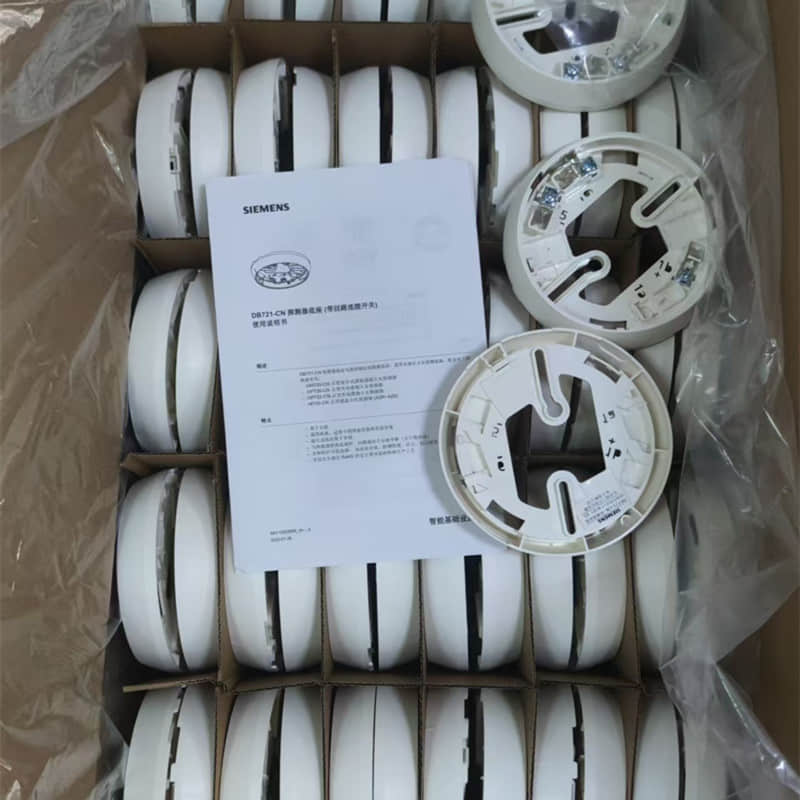
1.5 Required/Recommended Device Replacement:
Before replacing system equipment, be sure to prepare thoroughly. If you notice any traces of dirt on the device’s surface, clean it off using alcohol or an air dryer. Be sure to clean the device directly using water to prevent harming the circuitry.
Verifying that the new device’s model and order number match those of the old device is essential. Before you proceed, back up the current program completely from the host computer.
When replacing a device, ensure the system is completely powered off before proceeding. After you install the new device, turn on the system. Check that the device type in the software matches the latest hardware. If you see an error message, change the configuration and download immediately.
Finally, perform a comprehensive functional test to ensure proper system operation. You must remember that you cannot perform hot-swapping while powered on.
The heat detector may hurt you in this case. Also, you must verify the settings of the software following the replacement. Inadequately checking the settings can quickly lead to more problems and may even cause damage to the device.
2. Common Loop Line Faults and Solutions
Troubleshooting Siemens FS18 system circuits should follow the principle of “inside first, outside second, and segmented isolation.” First, determine the fault type based on the fault code displayed on the host computer.
This could be a short circuit, an open circuit, or a ground fault. Prepare to shut down the system to ensure life safety. If it persists, inspect the host loop card and interface board.
To troubleshoot external wiring, use the 50% segmentation method. Disconnect the wire from the junction box that is between the two loops. Use a multimeter to determine the resistance for each section. This will help you find the fault step by step.
After finding the faulty part, check for damage, loose wires, and other problems. After repairs, reconnect everything. Then, perform an electrical reset and test the device to ensure it functions properly.
l Note: Always consult the system wiring diagram. In the process of troubleshooting, take note of your resistance against the ground. When you segment, prioritize easily accessible junction boxes as the separation points.
2.1. Ground Faults:
Ground faults usually happen because of damaged insulation or the grounding of other equipment. If you are troubleshooting, begin by using the resistance setting on the multimeter. Avoid using the beeping setting. Check the resistance against ground to see if the fault exists.
Use the segmentation method. First, disconnect the host-side wiring. This will help you find the fault’s location.
Focus on the wet areas or conduit connections. Also, consider any third-party equipment that connects directly to the modules, such as elevators and dampers. Disconnect and measure each one individually.
After finding the fault point, repair or replace the damaged part. After the repair, measure the resistance to ground. This ensures regular operation before restarting power and doing an operational test.
2.2 Short Circuit Faults:
l Ensure that the circuit wires the isolation modules correctly. Use the segmentation function of the short-circuit isolator. This helps to separate the shorted circuit by disconnecting one segment at a time.
Pay special attention to equipment in humid areas. Check for water that could cause a short circuit. Also, look for any metal-to-metal contact or damage to cables in these connections.
After locating the short circuit point, dry or replace the water-infected equipment and repair the damaged circuit. After restoring the connection, retest the circuit resistance to confirm regular operation before resuming power.
2.3 Open Circuit Faults:
A circuit open fault usually appears as an incomplete loop. This happens mainly because of a break in the bus. Possible causes are:
Outside forces tear or dig up lines.
Loose terminals are coming off.
The system completely disconnects other lines after the operator activates the isolator. You should check the settings in the programming software. Set the circuit to loop mode, not branch mode.
When troubleshooting, use a multimeter in continuity mode. This lets you check the connections and disconnections in each loop.
Check the tightness of the terminals in each junction box. Look at the working conditions of all isolators. Also, check recent construction areas and line bends. Inspect for cable fatigue cracks at connections to equipment that people often move.
To fix this, first find the breakpoint. Then, reconnect or replace the damaged cable.
Ensure that you tightly fasten all terminals. After repair, measure the loop resistance to ensure it meets the requirements. Finally, confirm the correct loop configuration in the program before resuming regular operation.

2.4 Abnormality of Loop Cards:
If you experience a fault with the system loop, check first that the power and signal cables are connected to the card. Confirm the hardware DIP addresses on the loop cards. The loop card is only able to show one fault. If you find several faults, you will see them in this order: communication fault (card fault), short circuit (ground fault), and open circuit.
If this does not work, turn off the power and check that you have plugged in the card securely. If that does not work, you can turn off the power and ensure that the card plugs securely into the controller. If the problem happens again, remove all external loop connections and check again. Usually, this should solve the problem.
If the system returns to normal, it is most likely a problem on the line. Check whether the ground or a short circuit causes the issue.
Check the wiring on site, one section at a time. If the error continues, the loop card likely has a fault. Someone will need to replace it. If it is a fault in a single circuit, you can identify the issue directly.
3. Common Symptoms of Host Internal Failures
3.1 Repeated Reboots on the Host:
You need to reset your motherboard if the host program has malfunctioned or is outdated. Use special software to reflash your system program.
If the host reboots repeatedly, it usually happens because the backup power supply has failed or suffered damage. This usually occurs after an initial power failure, which can lead to the power module not starting.
Check if your mains input is stable. Measure the voltage of your battery. It should be higher than 21V. Replace any battery that has a low voltage or is not working.
This could indicate a problem if the computer freezes or restarts abruptly. A damaged chip or capacitor on the mainboard could cause this.
To troubleshoot, disconnect all field wiring and external circuit cards. Only leave the main power supply and a working battery. If the problem persists, technicians will consider it a mainboard fault and require a replacement.
Before performing a reset operation or reflashing, be sure to back up the program. You must perform all operations with the power off.
3.2 Circuit Card Communication Failure:
Check the status of the power and signal cables on the circuit board. Priority of faults: Communication failure > Card fault > Short circuit > Ground > Open circuit.
If the first restart doesn’t work, you can turn the controller off completely. Re-insert your card and check that you connected it correctly
Test the system by disconnecting all lines on site from the loopback card. If the system returns to normal, then the fault is at the line (short-circuit/ground fault).
Troubleshoot on-site lines by sections. You can trace the faults in a single loop directly to the line. All troubleshooting should follow the principles of first software, then hardware, and then isolation, before replacement.
3.3 Networking failure with too many hosts:
In the first place, check that the physical connection of the network meets specifications. All intermediate hosts must correctly set their motherboard terminal components, except for the first and final ones. They set them to OFF.
Ensure that the network settings of each host (IP address and subnet mask) are correct. This prevents address conflicts.
We need to optimize the topology of the network towards a star or linear structure. The rules strictly prohibit ring topology.
Check the network bandwidth to make sure it meets the data transmission needs. Check the firewall settings on your system. Ensure the Siemens communication port or any other data transmission port allows data packets to pass through.
If needed, turn off the firewall to test if the problem is policy blocking. Immediately restore the security settings after completion.
This tool tests connectivity and bandwidth. This tool helps ensure that network quality meets system requirements.
Inconsistencies in the host configuration:
Perform network-wide configuration sync when the master host software is updated. Before synchronizing, ensure that the devices in the region have the most recent program. To ensure consistency, all operations must follow the standard configuration. This includes the results of synchronization on each device.
4. Summary of other less common issues:
Some input/output modules in the 18S System are causing short circuits at output terminals 1, 3, and 4. This occurs when the jumper pin is in the J1 position. This happens during spot tests at the Beijing factory. You must bring this module into the host, start it, and then stop it before returning to regular operation.
The device type is correct. After programming it with the debugging program, however, there is a mismatch in type.
Then read the point that the host does not configure. Then, read the configuration files from the host using the software before reprogramming.
If the device connected to the input modules does not work, you may experience a monitoring problem.
Check first if the program reverses the module input. You can use the software to reverse the module input. You should set your input resistor at 3.3KO, not 680O.
Go from Level 1 to Maintenance. Find the device by searching the history log. Next, do an on-site inspection. Replace the device if the damage is severe.
This could indicate that someone broke it. Someone may need to replace it. The system may also be outdated, requiring an upgrade.
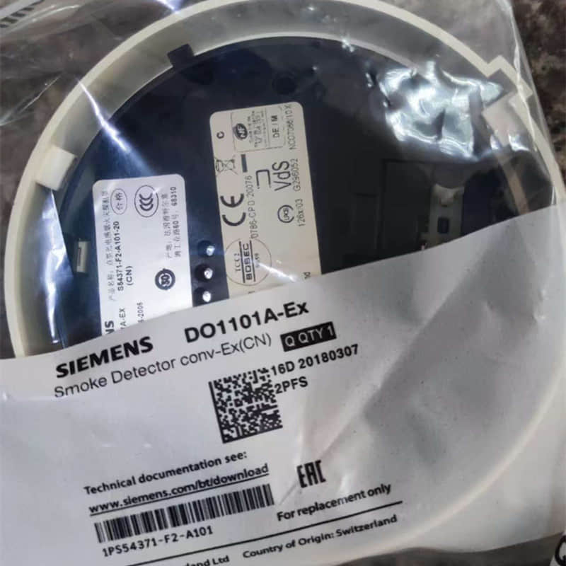
The central unit can only detect a small number of explosion-proof devices if there are several in the circuit. The explosion-proof manual switch alarm is to blame. This can lead to a voltage drop on the line.
The contractor, in an effort to cut costs, did not properly connect the equipment during the 18S wiring project. The loop instead created multiple branches and paralleled several others.
The host computer will short-circuit the loop when it restarts.
Determining the exact cause of the problem using a meter is difficult. Only unplug the circuit before every restart. Please wait until the computer has completely restarted before reconnecting it. Experts do not recommend using this method.
The host computer utilizes a multi-line three-wire system (output common and input). The fault light will turn on. The fault light will turn on if someone connects the input and standard multi-line wires incorrectly.
Wait for five minutes until it resets.
If your host computer has more than 10 display units, you will need to switch terminal 2 on the motherboard. Connect the display signal line.
This is an explanation for the Siemens 18 failure. I hope that it is helpful for everyone. You can share your opinions with others. You are welcome to consult if you have any queries.
For more information, please refer to the following:
Can FDF241-CN and FDF241-9 Wireless Room Temperature Sensor replace each other?
How to Build the Right PLC Control Cabinet?
Discover the Benefits of Installing a Siemens Smoke Detector in Your Company
Back to the top: Home / Blog