
Previous
Next
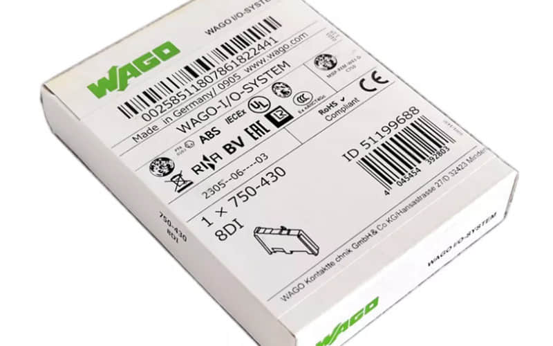
WAGO 750-430 8-Channel Digital Input Module: Comprehensive Technical & Installation Guide
1. Overview of WAGO 750-430
WAGO’s 750 Series is a high-grade, industry-proven modular I/O system. The wago 750-430 digital input module is ideal for demanding industrial automation environments.
Its robust design ensures high performance and strong electromagnetic compatibility (EMC) in harsh industrial settings. The wago 750 430 belongs to WAGO’s modular Fieldbus Coupler/Controller family, connecting smoothly with major industrial communication standards such as PROFIBUS, Modbus, EtherCAT, and Ethernet/IP.
Hot-Swappable Design: Allows you to replace the 750 430 module without shutting down the system, which is critical for continuous industrial operations.
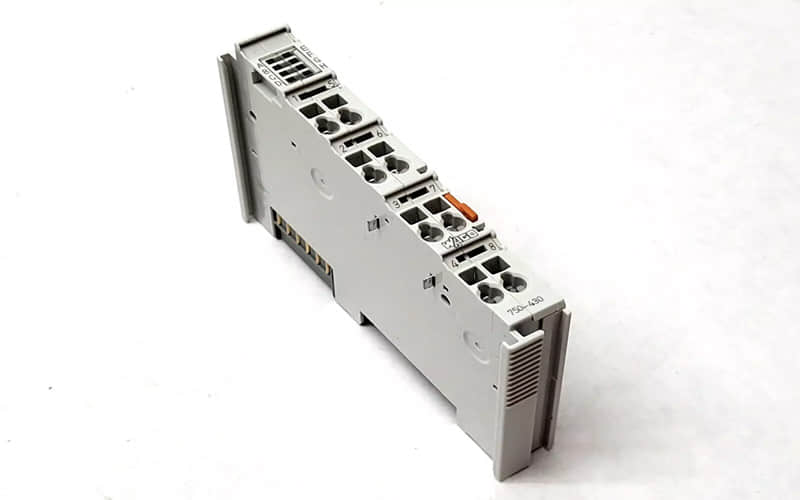
Space-Saving Build: The compact footprint saves space inside control cabinets, making it a strong choice for tight installation areas.
Reliability: Durable construction and high resistance to electrical noise keep the wago 750 430 running reliably under extreme conditions.
1.1 Features
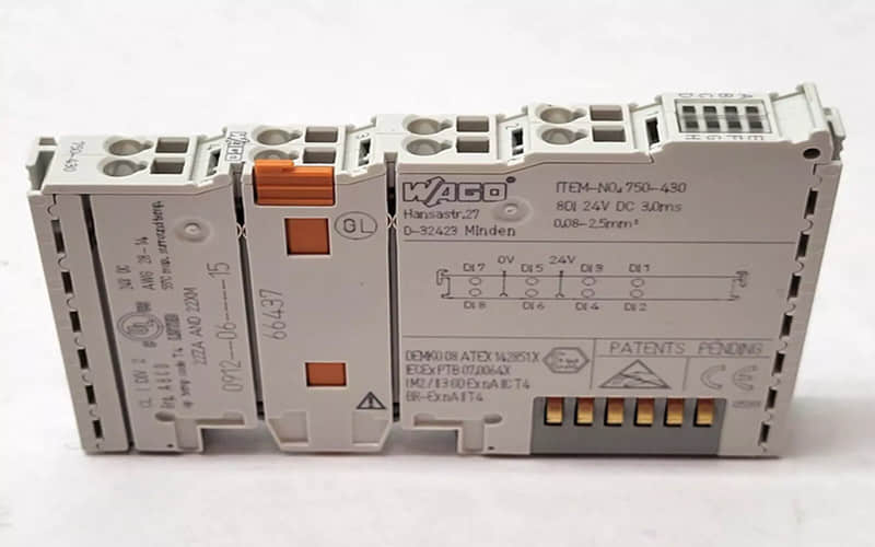
The wago 750-430 features eight configurable channels that support both sinking and sourcing operations. It integrates smoothly with 24V DC control systems, connecting to sensors, switches, and actuators without complications.
Real-Time LED Diagnostics: Each channel includes a status LED, giving you precise feedback for fast troubleshooting.
Scalable Expansion: The WAGO 750 Series allows you to add more I/O modules as your automation network grows.
1.2 Technical Specifications
Module Type: 8-Channel Digital Input Module (
wago 750-430)Input Voltage (24V DC): Sinking/Sourcing, 24V DC ($\pm20\%$)
Current Consumption: Typically 50 mA (without load)
Isolation Voltage: 500V (between field and system)
Protection Class: IP20 (for enclosure mounting)
Operating Temperature: $-25^\circ\text{C}$ to $+55^\circ\text{C}$ ($-13^\circ\text{F}$ to $+131^\circ\text{F}$)
Input Voltage High: 15V to 30V DC
Input Voltage Low: 0V to 5V DC
Input Current: Typically 3 mA per channel
Filter Time: Adjustable (typically 3 ms)
Max. Switching Frequency: 1 kHz
Certifications: IEC 61131, RoHS compliant
1.3 Applications
Process Control: Manages sensors, switches, and valves with precision, ensuring accurate signal processing and fast response times.
SCADA Integration: Smoothly connects with major PLC platforms via PROFIBUS, Modbus, and EtherCAT.
2. WAGO 750-430 Datasheet & Key Information
When reviewing the official wago 750 430 datasheet, engineers must verify signal ranges, wiring schematics, and environmental ratings. The module ensures high-speed signal acquisition with reliable short-circuit and overload protection.
Documentation Access: You can reference the complete technical data and pinout layouts directly through the standard wago 750 430 datasheet resources provided via authorized automation distributor networks.
3. Installation and Configuration
Mounting
Mount the wago 750-430 on a standard DIN rail (EN 60715). Snap the module onto a 35 mm rail and lock it securely in place.
Wiring
Use WAGO’s spring-cage clamping technology for secure, vibration-resistant connections (max. wire size: $2.5\text{ mm}^2$).
Follow the pinout diagram specified in the wago 750 430 datasheet to ensure correct signal wiring.
Configuration
Use WAGO e!COCKPIT or your PLC’s configuration tool (e.g., TIA Portal, CODESYS) to map the 750 430 input channels and adjust filter times or digital states.
4. Testing & Troubleshooting
Initial Power-Up Check
Power Check: Verify that the 24V DC power supply is correctly wired to the system bus.
LED Status: Check the PWR LED (should be solid green). If off, confirm voltage ($18\text{--}30\text{V DC}$) and check polarity.
Communication Check: Inspect the COM LED to verify active fieldbus communication.
Troubleshooting Common Issues
No Input Signal: Check for loose spring-cage wiring or misconfigured PLC input channels. Recheck terminal connections per the wago 750-430 wiring manual.
Erratic Signals: Address potential ground loops or electromagnetic interference by verifying proper shielding and grounding.
5. Related Part Numbers:
750-430/040-000: 8-channel digital input module designed with special settings for harsh environments.
Previous: Discover the Wago 750 504: A Deep Dive into Its Features
WAGO 750-301 PROFIBUS DP/FMS Fieldbus Coupler
WAGO 750-314 Fieldbus Coupler MODBUS
Back to the top: Wago Controller