1. Introduction
Life Safety Infrastructure Power
The fire alarm control panel (FACP) serves as the core of building life safety. The system relies on continuous and stable power to monitor the field, process signals, and coordinate evacuation. Power grid interruptions or power failures will cause the entire system to crash.
Cerberus PRO FC922 Application Positioning
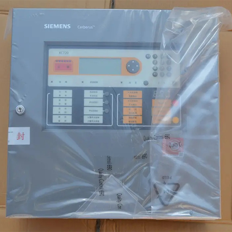
The Siemens Cerberus PRO FC922 intelligent fire alarm control panel is widely used in small and medium-sized commercial and industrial buildings. Its high-sensitivity detection and modular design place clear demands on power architecture. Proper power management supports daily operational stability and also functions as a mandatory indicator for passing fire inspections.
Core Theme
Using the Siemens FC922 host as an example, this guide explains its power supply modules.
It covers primary-to-secondary switching logic and load calculation methods.
It offers a reference for engineering selection and compliant design.
2. Power Architecture and Core Hardware Integration of the Host Panel
Primary and Secondary Power Configuration
The power system design of the FC922 fire alarm panel meets life safety reliability needs.
It focuses on seamless switching and smart management of primary and backup power sources.
Primary Power Access: The FC922 supports standard 120V/240V AC commercial power access as its primary power supply. It typically includes lightning protection modules and filter circuits. These reduce grid fluctuations and provide a stable base for later power conversion.
Secondary Power Supply: The system integrates 24VDC sealed lead-acid battery packs as standby power. When primary power fails, the system switches to battery power within milliseconds. This includes grid blackouts or voltage dropping below 187V for several seconds.
The switch is typically under 0.5 seconds. This ensures the controller keeps running. When designing backup reliability, factoring in a robust Siemens fire alarm panel battery backup configuration ensures uninterrupted code compliance during emergencies.
Switching Logic and Intelligent Management: A microprocessor-controlled smart module manages switching. It usually uses magnetic latching relays. It prevents false equipment actions.
Meanwhile, the system uses an intelligent charging circuit. It adjusts charging settings based on ambient temperature and battery traits.
This helps prevent overcharging. It also monitors internal resistance to assess battery degradation. Once primary power recovers, the system automatically switches back and initiates float charging for the standby batteries.
Main Board Built-in Power Module
The FC922 main board integrates a high-efficiency regulated power supply board, undertaking two critical tasks:
Internal System Logic Power: Supplies clean, stable voltages, such as 5VDC or 3.3VDC. It powers core logic circuits, including the main processor and communication modules. It also powers the display and operation panels. This ensures stable program execution.
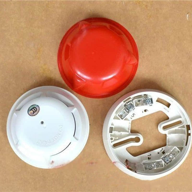
Loop Device Driving: Powers detectors, modules, and other field devices over a two-wire bus. Siemens C-NET or equivalent.
This two-wire technology sends both power and data over one pair of wires. It uses voltage and current from the Siemens FC922 power supply board. This module features automatic overcurrent protection and dynamic power distribution at maximum capacity to prevent supply shortages.
Voltage and current supplied directly by the Siemens FC922 power supply board. When you have unexpected communication drops or anomalies from these loop devices, use this guide.
It helps you troubleshoot common loop fault signals.
You can quickly find wiring and polling issues.
Core Hardware & Part Numbers Reference Overview
To streamline system integration and project procurement, the standard hardware components and ordering part numbers associated with the FC922 power and control architecture are structured below:
Category | Component / Module | Typical Part Number Reference | Core Function |
Panel Core | Intelligent Fire Alarm Control Panel | FC922-AZ | Centralizes system logic, display, and alarm handling |
Power System | Main Power & Charging Module | FCA2015-A | AC-to-DC conversion and intelligent float charging management |
Backup Energy | Sealed Lead-Acid Battery Pack | 12V / 12Ah or 24Ah | Provides 24-hour emergency backup endurance during grid failure |
Field Bus | C-NET Expansion & Driver Card | FCL2001-A | Connects and drives detectors, manual call points, and loop modules |
Expansion Accessory | Remote NAC Extender | FAC-2 / FCA2018-U | Resolves line drop issues for long-distance notification appliances |
3. Dedicated Expansion Accessories and Modules
To handle complex, large-scale fire safety system demands, the FC922 supports multiple dedicated expansion accessories to enhance power capacity and control flexibility.
Remote Notification Appliance Circuit (NAC) Extenders
Function: In large-span spaces, like massive shopping malls or industrial plants, long horn/strobe wiring can cause voltage drops. This can prevent terminal devices from starting up. NAC extenders (such as FAC-2 or compatible modules) act as local power repeaters.
They receive control signals from the main panel.
They use local 24VDC power to drive notification appliances.
This helps fix voltage drop and low current issues.
Configuration Requirements: Ensure extender output current meets the inrush demands of attached loads (especially capacitive loads) and verify terminal voltages under full load conditions.
Intelligent Addressable Power and Control Modules
Function: These addressable devices (such as Cerberus PRO intelligent input/output or power monitor modules) execute dynamic zone-specific power switching and status monitoring.
Application Scenarios:
Dynamic Power Switching: Selectively cuts non-fire power within designated fire zones or activates emergency lighting upon alarm confirmation.
Status Monitoring: Tracks controlled devices (like smoke dampers or exhaust vents) and reports status signals back to the panel.
Isolation and Protection: Built-in isolation guards against high-voltage incursions into the signaling loop.
4. Load Calculation and Sizing
1. Standby vs. Alarm Consumption
In power capacity planning, keep consumption separate for standby monitoring and dynamic fire alarm states. Their output needs differ greatly.
Standby Current: Total current consumed by all devices under normal monitoring without alarms or faults. Most input/output modules draw around 5mA during polling. This metric sets the baseline operating costs. It also serves as the basis for sizing the Siemens fire alarm panel battery backup for 24 hours.
Alarm Current: Maximum current consumed when all interlocked notification and control devices activate simultaneously or sequentially. Startup surges can reach 7 to 10 times polling levels. This determines the maximum capacity required for the Siemens FC922 power supply modules under peak activation.
2. Loop Device Consumption and Line Drop
Calculating loop device loads requires cumulative summation of individual static and dynamic parameters across detectors, manual call points, modules, and notification appliances.
Key Constraints: Manage voltage drop on long cable runs. This keep terminal voltage above operating limits. Mitigation strategies include:
Staggered Control: Programming software delays to stagger high-current device start times.
Additional DC24V Trunks: Distributing loads across multiple power lines to minimize resistance.
Increased Wire Gauge: Deploying thicker conductors over long distances.
3. Battery Backup Duration Sizing
Backup battery sizing must follow stringent engineering standards like NFPA 72 fire alarm load calculation parameters or regional equivalents.
Calculation Formula:
Required Capacity (Ah)=
Depth of Discharge Coefficient
(Standby Current×24h)+(Alarm Current×Alarm Duration)
Design Parameters: Lead-acid depth of discharge should not exceed 80% (coefficient 0.7 to 0.8). For example, a system with a 2A standby current and a 5A alarm current may need about 90Ah.
This assumes 24 hours of standby, followed by 3 hours of alarm operation.
5. Regulatory and Compliance Standards
1. NFPA 72 and Local Codes
In regions that use North American standards, fire alarm power systems must meet **NFPA 72** load calculation rules. They must also follow other related codes.
Standby and Alarm Durations: Systems must support 24 hours of standby. Then they must support 5 minutes of alarm operation. Voice evacuation systems must support 15 minutes of alarm operation. Power supplies must exceed full-load needs by at least 120%.
They must recharge fully drained batteries to 80% capacity within 48 hours.
Circuit Protection Limits: Primary AC mains supplies must not include residual current devices (RCDs).
They must not include overload trip mechanisms that could cause unintended power loss in emergencies. Line voltage drops under full load must not exceed 10%.
2. UL/FM Certification Requirements
Deploy a UL-listed fire alarm power supply. Use matching components. This requirement ensures compliance with the code. It also helps protect your insurance coverage.
System Integrity: The FC922 panel and matching power boards must maintain formal listings under standards like UL 864. Using non-certified third-party hardware voids system listings. It can lead to denied insurance claims after incidents. It may also violate local codes.
Componentis Compatibilitas: Partes genuinae efficiunt ut undulatio tensionis, compatibilitas electromagnetica (EMC), et rationes oneris congruant.
Hae res congruunt cum circuitu intelligentis administrationis potentiae architecturae Cerberi PRO.
Ita directe explent requisita potentiae Cerberi PRO.
3. Submittal and AHJ Requirements
Projects must submit an engineering package.
It must include load summaries, voltage drop calculations, and battery sizing worksheets.
This helps satisfy the Authority Having Jurisdiction (AHJ) during plan review and commissioning.
6. Troubleshooting and Maintenance
1. Common Fault Codes
Rapidly interpreting panel diagnostics streamlines prompt restoration:
AC Loss: Main power input interrupted, tripped breakers, or voltage fluctuations exceeding acceptable tolerances. The system shifts to battery power.
Low Battery: Indicates degraded capacity, sulfation from prolonged float charging, or loose terminal connections. When paired with simultaneous AC loss alerts, suspect a failed internal charging board.
Ground Fault: Insulation resistance dropping below acceptable thresholds (typically under 20MΩ), often triggered by moisture ingress or damaged insulation.
Often triggered by moisture ingress or damaged insulation. For full steps to replace faulty field hardware after you locate the fault, see the Siemens fire detector replacement guide.
2. Diagnostic Tools and Procedures
Systematically isolate issues using digital multimeters, clamp meters, and insulation resistance testers (megohmmeters). Use Siemens fire alarm troubleshooting software to review diagnostic logs and confirm device status.
3. Preventive Maintenance Best Practices
Battery Lifecycle: Sealed lead-acid batteries feature a typical chemical lifespan of 3 to 5 years. Initiate rigorous annual load testing starting in year three and replace units prior to year five.
Verification: Always utilize certified components and execute full charge-discharge verification routines following maintenance interventions.
7. Conclusion and Procurement Guidance
1. Core Summary
Designing strong life safety systems depends on accurate power budgeting.
It also requires code compliance, such as NFPA 72 fire alarm load calculations.
It must also meet Cerberus PRO power requirements. Managing standby reserves correctly protects facilities against unexpected grid failures.
2. Professional Procurement Support
To keep system warranties and pass AHJ inspections, buy UL-listed fire alarm power supply parts.
Get Siemens fire alarm troubleshooting and replacement hardware only from authorized distributors and certified life safety integrators.
Protects facilities against unexpected grid failures. To broaden your understanding of industrial automation and component sourcing in the Cerberus PRO ecosystem, read our insights.
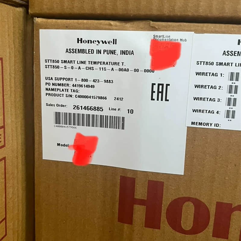
Review our best practices for sourcing smartline transmitters.
Explore More Formats & Join the Discussion:
If you prefer to review this information in alternative formats or want to connect with our engineering community, you can access our resources across multiple platforms:
SlideShare: View and download the structured presentation summary on our official Siemens FC922 Fire Alarm Power System & Load Calculation Guide
Scribd: Read and share the complete technical document on our Technical Guide: Siemens Cerberus PRO FC922 Fire Alarm Control Panel Power System & Load Calculations
LinkedIn: Join the technical conversation, share your industrial automation experiences, and follow our updates on Ensuring Reliability: Siemens FC922 Fire Alarm Power & Load Design