1. Introduction
In process automation, measurement accuracy is everything. Whether you are managing chemical reactions, refining oil, or running a power plant, inaccurate readings lead to inefficient operations, off-spec product batches, or costly plant shutdowns. Keeping your instrumentation precise is a non-negotiable part of plant maintenance.
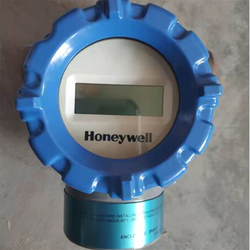
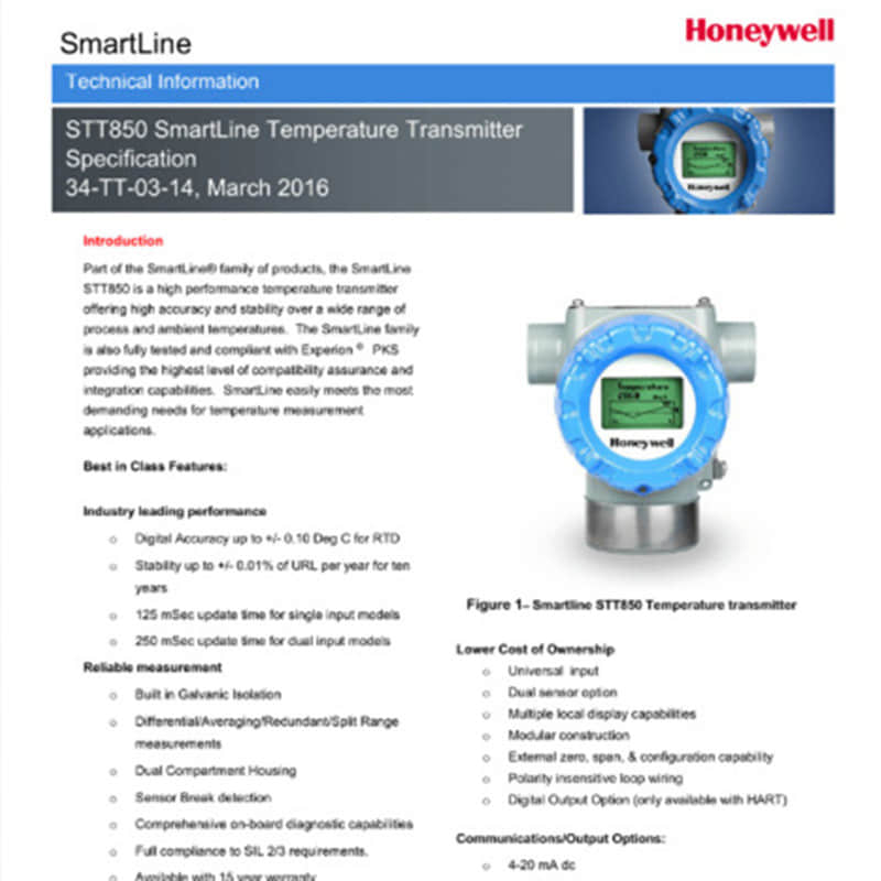
Drawing from years of hands-on field service and industrial automation supply operations, we know that technicians need fast, reliable answers without wading through hundreds of pages of manuals. Among industry benchmarks, the Honeywell STT850 temperature transmitter is widely recognized for its exceptional long-term stability, advanced diagnostics, and dual-sensor capabilities.
Among industry benchmarks, the Honeywell STT850 temperature transmitter is widely recognized... If you are still evaluating your hardware tier for a specific application, check out our comparison on Honeywell STT850 vs. STT750 models to ensure it fits your exact process requirements...
However, even the most robust instruments require periodic calibration to maintain peak performance and regulatory compliance. If you are pressed for time during a turnaround or routine maintenance check, here is a practical field guide on how to calibrate Honeywell SmartLine transmitter models in about 10 minutes, using the STT850 as our benchmark.
2. Tools & Preparation Checklist
Before initiating calibration on your Honeywell STT850 temperature transmitter, ensure your hardware and safety protocols are fully in place. Precision industrial maintenance leaves no room for shortcuts.
Required Hardware Overview
Tool | Purpose |
HART Communicator / SmartLine Device Manager | For digital configuration and SmartLine Device Manager configuration workflows |
Precision Calibrator (RTD/TC source) | To simulate exact temperature inputs |
24V DC Loop Power Supply | To power the transmitter during bench or field calibration |
Digital Multimeter | To verify 4-20mA loop current output accuracy |
Calibration Soft Tubing (e.g., Tygon 1/8" ID × 1/4" OD) | For pressure or leak testing if integrating loop accessories |
Safety & Isolation Protocols (LOTO Procedures)
In active industrial environments, Lockout/Tagout (LOTO) protocols are mandatory before servicing any field device:
Identify the Loop: Confirm that your target STT850 is mapped correctly to your control system (such as an Experion® PKS architecture).
Isolate the Loop: Place the loop in manual or bypass mode at the DCS level to prevent unintended process trips or upsets.
Lock Out Power: Disconnect and mechanically lock the 24V DC supply feeding the transmitter loop.
Tag the Device: Apply a standard LOTO warning tag stating "Under Calibration – Do Not Operate".
Verify Zero Energy: Use a digital multimeter to confirm that zero voltage and current are present at the transmitter terminals before handling internal wiring.
⚠️ Field Warning: While the STT850 features built-in electrical isolation and advanced self-diagnostics, electronic self-checks never replace physical LOTO verification. Always treat the hardware as live until tested.
3. Step-by-Step Calibration Procedure for Honeywell STT850
Step 1: Connection & Communication (2–3 mins)
24V DC Loop Power Supply: Connect to the STT850 terminals (note: the device features built-in reverse polarity protection, allowing arbitrary polarity wiring).
HART Communicator / PC: Connect a HART communicator or a laptop running SmartLine Device Manager configuration software across the loop.
Precision Calibrator: Hook up your RTD or thermocouple source to the transmitter input terminals.
Digital Multimeter: Insert in series to monitor active loop current.
Establishing Digital HART Connection
Power Up: Energize the loop. The STT850 initializes within approximately 2.5 seconds.
Launch Software: Open your management software on your PC. This environment streamlines Digital Enhanced (DE) protocol management.
Go Online: Select online mode and scan for connected network devices.
Confirm Device Parameters: Verify the device tag, firmware version, and sensor configuration. Because the STT850 supports dual-sensor input, confirm whether you are calibrating Input 1, Input 2, or both.
Check Protocol Mode: Ensure the transmitter operates in 4–20mA DC or HART® (version 7.0) mode for standard calibration.
Field Pro Tip: The STT850 provides external zero, span, and configuration capabilities directly via local buttons without opening the housing, significantly cutting down service time in harsh field locations.
Once online, verify your device tag and configuration parameters. If you encounter initialization hurdles during this phase, you can refer to our guide on how to fix Honeywell STT850 configuration errors during commissioning before proceeding with the sensor trim
Step 2: Zero and Span Trim (Sensor Trim) (3–4 mins)
Applying Lower Range Value (Zero Trim)
Simulate LRV: Set your precision calibrator to the lower range value (LRV)—for example, 0°C for a 0–100°C measurement span.
Input Configuration: For RTD inputs, use a precision resistance box or RTD simulator. (Note: The STT850 supports direct entry of Callendar-Van Dusen coefficients—R0, $\alpha$, $\delta$, $\beta$—for high-accuracy calibrated RTD sensors). For thermocouples, use a TC calibrator with cold junction compensation.
Navigate Software: Open the Sensor Trim or Calibration menu in your software suite.
Execute Trim: Select Zero Trim and follow the software prompts to confirm the applied input.
Tolerance Check: The STT850 features an RTD digital accuracy of 0.10°C; your post-trim zero reading should fall comfortably within this threshold.
Applying Upper Range Value (Span Trim)
Simulate URV: Set your calibrator to the upper range value (URV)—for example, 100°C.
Execute Span Trim: In the software menu, select Span Trim (or Full Scale Trim).
Save Adjustment: Confirm the applied reference value to let the transmitter adjust its internal characterization. The STT850 maintains an exceptional long-term stability of 0.01% of URL per year for up to 10 years.
Verification
Cycle between LRV and URV inputs to verify transmitter linearity as part of any robust industrial pressure and temperature calibration guide.
Single-input models update in 125 ms, while dual-input models update in 250 ms. Always allow readings to stabilize before logging values.
Step 3: Output Trim (4–20mA Loop Calibration) (3–4 mins)
Why Output Trim Matters
Sensor trim aligns how internal electronics interpret the process variable, but output trim guarantees that the analog 4–20mA signal accurately represents that data downstream to your DCS or PLC.
Performing the Output Trim
Hold Stable Input: Keep the precision calibrator active at a stable mid-span point (typically 50% of range, e.g., 50°C).
Access Output Trim: Navigate to the Output Trim (or Analog Output Trim) menu in your Device Manager software.
Trim the 4mA Point: Command the transmitter to force an output near 4mA, measure the actual current using your in-series digital multimeter, and enter the measured value. The transmitter will automatically adjust its internal DAC.
Trim the 20mA Point: Command the software to force an output near 20mA, measure the actual current, and input the exact value to complete two-point linearization.
Verification of Loop Accuracy
Verify loop linearity across three test points: 4mA (0%), 12mA (50%), and 20mA (100%).
The STT850's built-in galvanic isolation ensures loop output remains stable even in electrically noisy industrial environments.
Cross-check the Primary Variable (PV) digitally via HART to ensure it matches the analog output within specifications.
Final Checks & Quick Troubleshooting
Final Quality Checklist
Run a quick diagnostic cycle via the device interface to ensure no active sensor break or hardware faults exist.
Verify that NAMUR 107 extended diagnostics or NAMUR line-fault detection functions are active if required by plant standards.
Record your "as-found" and "as-left" values in the site calibration logbook.
Field Troubleshooting Quick Reference
Issue | Likely Cause | Solution |
HART communicator connection fails | Loop resistance out of spec or wiring error | Verify total loop resistance (should be 250–1100 $\Omega$ for HART). Note that STT850 handles arbitrary polarity. |
Output stuck at 4mA or 20mA | Sensor failure or configuration mismatch | Run full internal self-diagnostics to isolate channel faults. |
Readings drift post-calibration | Ambient temperature shift | Allow 5–10 minutes for thermal stabilization; the STT850 compensates dynamically for ambient effects. |
Dual input shows channel mismatch | Asymmetric sensor calibration | Calibrate each input channel independently (the STT850 supports differential, average, redundancy, and split-range modes). |
Summary: 10-Minute Calibration Checklist
Step 1: Connect loop power, HART communicator, and precision calibrator (2 min)
Step 2: Establish communication via SmartLine Device Manager configuration (1 min)
Step 3: Perform zero trim at lower range value (LRV) (2 min)
Step 4: Perform span trim at upper range value (URV) (2 min)
Step 5: Perform 4mA analog output trim (1.5 min)
Step 6: Perform 20mA analog output trim (1.5 min)
Total Execution Time: 10 min
4. Pro Tips & Troubleshooting Common Field Issues
Handling Stubborn Zero Shifts
Zero shifts are among the most frustrating field issues when executing a standard Honeywell STT850 calibration routine. Here is how to systematically diagnose and resolve them.
Common Causes of Zero Shift
Cause | Symptom | Diagnostic Approach |
Thermal effects | Zero drifts as ambient temperature changes | The STT850's ambient limits range from -40°C to 85°C—verify your environment stays within this range. |
Mounting stress | Zero offset after installation | Check for pipe strain or vibration—the STT850 housing is rugged, but mechanical stress can distort readings. |
Moisture ingress | Intermittent zero drift | Inspect the dual-compartment housing; the electronics compartment must remain hermetically sealed. |
Loop power fluctuations | Zero shifts with supply voltage changes | The STT850 requires a stable 24V DC loop power source; use a regulated supply during calibration. |
Step-by-Step Zero Shift Troubleshooting
Isolate the Source: Disconnect the sensor input and apply a known zero value (e.g., short RTD leads for a 0°C equivalent).
Check the Output: If the output reads 4mA with zero input, the fault lies in the sensor or wiring, not the transmitter.
Perform a Sensor Trim: Use the HART communicator to execute a zero trim, resetting the internal reference.
Verify with a Second Calibrator: Cross-check your precision calibrator against a known-good secondary unit to rule out tool error.
Field Pro Tip: When troubleshooting Honeywell pressure transmitter zero shift or temperature offset issues, always run the built-in diagnostic suite before attempting manual adjustments.
Handling Communication Drops
Communication drops with your HART communicator or management software disrupt workflow. Use this quick recovery checklist:
Loop Resistance: HART requires a minimum loop resistance of 250Omega. Verify your loop has adequate resistance between the power supply and communicator.
Polarity Check: While the STT850 supports arbitrary polarity on power terminals, ensure correct polarity if using an external HART modem.
Power Cycle: Disconnect and reconnect the 24V DC supply to clear transient communication lockups.
Multi-Drop Conflicts: If multiple HART devices share the loop, verify that each device has a unique polling address configured.
When Communication Fails Completely
Verify Power: Measure the voltage directly at the STT850 terminals; it should register between 12V and 42.4V DC.
Check Physical Damage: The STT850 features a modular display that can be swapped without replacing the entire unit. If the screen is blank but power is present, the display module may need replacement.
Use Backup Controls: The STT850 supports local external configuration via pushbuttons without opening the housing, allowing basic zero/span adjustments even without digital links.
Standard Trim vs. Full Factory Reset
Choosing the right level of intervention prevents unnecessary downtime and loss of configuration data.
Standard Trim (Recommended for Routine Calibration): Use for annual or biannual calibration cycles, minor drift within 0.5% of span, or post-installation mounting stress relief. Adjusts sensor or output trim while preserving configuration parameters. Completes in under 2 minutes.
Full Factory Reset (Use Sparingly): Use only for devices in service for 10+ years showing severe drift, suspected corrupted configuration data after a power surge, or taking over a misconfigured unit. Restores all parameters to factory defaults and requires complete reconfiguration.
⚠️ Field Warning: A full factory reset should always be your last resort. Document all custom configuration parameters before proceeding.
Decision Flowchart
Zero shift < 0.5% span? $\rightarrow$ Perform standard sensor trim.
Zero shift > 0.5% span & Device > 10 years old? $\rightarrow$ Consider factory reset and full recalibration.
Zero shift > 0.5% span & Device < 10 years old? $\rightarrow$ Check for mounting stress, EMI, or moisture. If no physical issue is found, use a factory reset as a last resort.
5. Conclusion & Maintenance Best Practices
Summary of Calibration Intervals
The Honeywell STT850 temperature transmitter is engineered for exceptional long-term stability, directly dictating practical calibration scheduling. Based on performance specs and field experience, recommended maintenance intervals include:
Application Type | Recommended Interval | Rationale |
Standard industrial processes | 12 months | Industry baseline for critical loop accuracy |
Non-critical / monitoring only | 24 months | Leverages the STT850's 0.01% URL/year stability |
SIL 2/3 safety loops | 6–12 months | Compliance mandate for functional safety |
Harsh environments (high vibration/extremes) | 6 months | Mitigates accelerated drift from severe stress |
Key Stability Advantage: The STT850 maintains $\pm 0.01\%$ of URL per year for ten years. For a standard RTD input, expected drift over an entire decade remains minimal (typically $<0.1^\circ\text{C}$). This allows plants to safely extend calibration intervals and lower operational costs without sacrificing measurement integrity.
Maintenance Best Practices for Long-Term Reliability
Leverage Built-In Diagnostics: The STT850 features comprehensive on-board diagnostics (including NAMUR 107 extended diagnostics and automated sensor break detection) that reduce unnecessary physical bench calibration.
Environmental Considerations: Install proper conduit seals to prevent moisture migration into wiring entries. Inspect housing O-rings for cleanliness and structural integrity during every calibration cycle.
Documentation & Trend Analysis: Maintain a digital calibration database recording exact "as-found" and "as-left" values. Because of the 10-year stability guarantee, you should observe consistent, flat trendlines year-over-year.
Upgrade Path & Component Management: The STT850's modular architecture permits component-level swaps—such as display modules, communication boards, or sensor input modules—without replacing the entire transmitter assembly.
Explore More Formats & Join the Discussion:
If you prefer to review this information in alternative formats or want to connect with our engineering community, you can access our resources across multiple platforms:
SlideShare: View and download the structured presentation summary on How to Calibrate Honeywell STT850 in 10 Mins
Scribd: Read and share the complete technical document on our Honeywell STT850 Temperature Transmitter Field Calibration and Troubleshooting Manual
LinkedIn: Join the technical conversation, share your industrial automation experiences, and follow our updates on Fast Field Calibration Guide: Honeywell STT850 Temperature Transmitter