1. Introduction: The Critical Role of Addressable Modules in Commercial Life Safety
In modern commercial and industrial life safety infrastructure, the architecture of fire detection and notification has shifted decisively away from legacy, hardwired zone panels. Traditional systems relied on kilometers of copper running from every single sensor, switch, and notification appliance straight back to a centralized control cabinet—a method that proved labor-intensive, inflexible during facility expansions, and difficult to troubleshoot.
Today's complex facilities—ranging from high-rise office towers and sprawling manufacturing plants to hazardous chemical storage facilities—rely on distributed addressable fire alarm systems. At the heart of this architecture are addressable monitor and control modules. These intelligent interface devices bridge the gap between the main fire alarm control panel (FACP) and auxiliary mechanical, electrical, and life safety systems, allowing individual devices to communicate precise status, location, and diagnostic data over a shared Signaling Line Circuit (SLC) loop.
The Installation Challenge: Compliance, Timelines, and Precision
For electrical contractors, fire alarm technicians, and system integrators, deploying these modules under real-world job site conditions presents distinct hurdles:
Tight Project Timelines: Commissioning schedules are frequently compressed, leaving little room for rework or wiring errors during final building inspections.
Strict Code Compliance: Installations must strictly adhere to NFPA 72, local electrical codes, and manufacturer specifications to avoid costly inspection failures or regulatory liabilities.
The Cost of Commissioning Errors: A single miswired terminal, missing end-of-line (EOL) resistor, or addressing conflict can trigger persistent trouble signals, delay building sign-off, and consume valuable labor hours in fault-tracing.
Ecosystem Overview: Focusing on High-Rotation Hardware
Navigating this landscape requires deep familiarity with industry-standard hardware ecosystems, most notably the Siemens Cerberus PRO and S-series platforms.
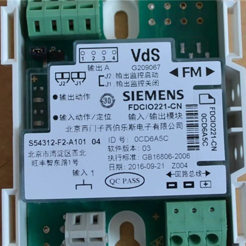
Within this ecosystem, certain components see exceptionally high rotation in retrofit and new-construction projects due to their versatility. Among them, the Siemens FDCIO422 Input/Output Module stands out as an indispensable workhorse. Designed to monitor dry-contact input devices (such as waterflow switches, tamper switches, and supervisory points) while simultaneously providing relay output control for notification appliances, smoke dampers, or door holders, the FDCIO422 encapsulates the core challenges and best practices of modern addressable installation.
The following sections provide a definitive, field-tested methodology to handle pre-installation planning, precision wiring, rapid commissioning, and systematic troubleshooting for these critical life safety assets.
2. Pre-Installation Planning & Hardware Checklist
Before deploying Siemens fire alarm modules (such as the FDCIO422) on-site, rigorous advance planning serves as the first line of defense to ensure the stable operation of the entire life safety system. Ignoring preliminary verification often leads to rework or false alarms in the field.
Compatibility Verification
System Matching: Prior to ordering and installation, you must confirm that the main control panel's firmware version is fully compatible with the module series (such as Siemens Cerberus PRO, Desigo CC, or FC series panels). Hardware version mismatches will result in bus recognition failure.
Loop Capacity: Evaluate the load margin of the Signaling Line Circuit (SLC). For analog addressable systems, each detection loop typically supports a maximum of 200 devices (including detectors, manual call points, and interface modules), ensuring that static and dynamic currents after adding new modules do not exceed the panel's power supply design specifications. When performing overall system planning and capacity evaluation, it is recommended to reference Siemens Fire Alarm Panels: Understanding Power Supply Requirements for deeper insights into power configuration details.
Tool and Cable Preparation
Professional Tools: Prepare a digital multimeter, loop tester, DIP switch configuration tool, and standard insulated screwdrivers to check line continuity, insulation resistance, and module address settings.
Wiring Standards: Compliant Shielded Twisted-Pair cables must be used. In industrial or high-rise building environments subject to severe electrical interference, single-ended shield grounding is crucial for eliminating electromagnetic interference (EMI).
Environmental and Installation Specifications
Physical Protection: Modules should be installed in areas away from strong mechanical vibrations (such as direct mounting brackets on large compressors or fan rooms) to prevent loose wiring or internal component damage caused by vibration. When necessary, use rubber damping pads or relocate to an independent wall surface.
Temperature and Humidity Control: Protect modules from moisture erosion, especially when installing in basements, outdoors, or near water sources, by using appropriate protective enclosures. Simultaneously, ensure that the temperature inside the cabinet remains within the equipment's allowable operating range to prevent extreme environments from shortening electronic component lifespans.
System Design Reference Standards
During planning and installation, reference the following international standards to ensure compliance:
ISO 7240-14: Covers the design, installation, commissioning, and maintenance of fire detection and fire alarm systems in and around buildings.
NFPA 72: National Fire Alarm Code, a core global standard widely used for fire protection installations.
TS 54-14: European technical specification providing guidelines for planning and application of fire detection and fire alarm systems.
3. Step-by-Step Installation Instructions (Focusing on FDCIO422)
The FDCIO422 is a versatile input/output module widely used in Siemens fire alarm systems. The following steps guide you through its rapid installation and commissioning.
Step 1: Physical Mounting & Enclosure Integrity
The FDCIO422 module supports both DIN rail mounting and surface mounting methods. Ensure the enclosure remains completely sealed during installation to prevent dust and moisture ingress.
DIN Rail Mounting: Align the module clips with the DIN rail and press downward until an audible "click" is heard, ensuring a secure lock.
Surface Mounting: Use the mounting holes at the bottom of the module to secure it to a flat, dry wall surface using screws.
Grounding Technique: Proper grounding is mandatory to prevent electromagnetic interference (EMI). Use 16 AWG or heavier grounding wire to connect the module ground terminal to the enclosure's common grounding point. Ensure the ground loop resistance is less than 1 ohm. Good grounding not only suppresses EMI but also enhances system survival during lightning or surge events.
Step 2: Addressing Configuration
Each FDCIO422 module must have a unique address on the SLC (Signaling Line Circuit) loop to prevent communication conflicts.
Using Programming Tools: Connect to the module's programming port using a dedicated Siemens programmer (such as the FCA1804) to set the address via software. This method is the most accurate and suitable for batch configuration.
Using DIP Switches: A set of DIP switches is typically provided on the module for address setting. Refer to the address table on the module label and set the switches to the corresponding positions. For example, setting switches 1 and 3 to the ON position may correspond to address 5. Note: The address range is typically 1-200, depending on system capacity.
Common Mistake: Setting duplicate addresses will cause communication failure across the entire SLC loop. After configuration, use a loop tester to verify the address uniqueness of every module.If you wish to further standardize your configuration workflow and avoid common parameter errors, you can refer to Siemens Fire Alarm System: How to Correctly Program a Device.
Step 3: Precision Wiring Guidelines
Correct wiring is the key to stable system operation. Wiring for the FDCIO422 module is divided into three categories: SLC loop, input dry contacts, and output control relays.
Connecting the SLC Loop: The SLC loop is the communication channel between the module and the control panel. Pay attention to polarity during wiring: typically the "+" and "-" terminals must not be reversed. Use shielded twisted-pair cable (recommended 18-16 AWG) and ground the shield at a single point at the control panel. Total loop length should not exceed the manufacturer's specified maximum (typically 3,000-4,000 feet). Polarity Sensitivity Check: If the module fails to communicate after wiring, swap the two wires at the SLC terminals.
Wiring Input Dry Contacts: Input channels are used to connect external dry-contact devices, such as waterflow switches and supervisory valves. Connect the normally open or normally closed contacts of the device to the module input terminals. For normally open contacts, modules typically provide internal pull-up resistors; for normally closed contacts, an EOL resistor may need to be wired in series for line supervision. Note: Input wiring should be kept away from high-voltage power lines, maintaining a separation of at least 2 inches to prevent induced noise.
Wiring Output Control Relays: Output channels are used to control external devices, such as notification appliances, smoke dampers, and door holders. Outputs are categorized into power-limited and non-power-limited loads.
Power-Limited Loads (e.g., Notification Appliance Circuits): Use 18-16 AWG wire and connect an EOL resistor at the end of the circuit. Module outputs are typically 24VDC with a maximum current limit of 2A.
Non-Power-Limited Loads (e.g., Fire Pump Starters): Relay isolation matching the rated voltage and current must be used. Module outputs provide dry-contact signals only and do not directly drive high-current equipment. Follow local electrical codes during wiring to ensure adequate conductor cross-sectional area.
Step 4: End-of-Line (EOL) Resistor Placement
The EOL resistor is a critical component for line supervision in fire alarm systems. Missing or mismatched resistor values are primary causes of trouble signals.
Placement Location: The EOL resistor must be installed on the very last device of the circuit, not at the module terminals. For instance, on an output circuit, the resistor should be connected to the terminals of the final notification appliance.
Resistance Selection: Use the specific resistance value designated for the module (typically 4.7 kΩ or 10 kΩ, as specified in the module manual). Mixing different brands or series of modules may require different values, and mismatching will lead to false alarms.
Wiring Method: Directly solder or crimp the resistor between terminals and insulate properly. Avoid long lead wires, which can introduce extra resistance or interference.
Verification: After installation, use a multimeter to measure loop resistance at the module terminals. For normally open contact input loops, measure the EOL resistance value; for normally closed contact loops, measure a near-short value (approximately 0 ohms). If measured values are abnormal, check the wiring and resistor placement.
4. Commissioning and Quick-Check Verification
After completing the physical installation and wiring of the FDCIO422 module, the next steps involve system power-up commissioning and quick-check verification. This section guides you through confirming correct module recognition, interpreting status LED indicators, and ensuring electrical parameters remain within normal ranges.
Panel Auto-Programming vs. Manual Mapping
Siemens fire alarm control panels (such as the FC922/FC924/FT924/FV922/FV924 series) support two module identification methods: auto-programming and manual mapping.
Auto-Programming: This is the quickest verification method. Enter programming mode on the panel and select the "Auto-Learn" or "Auto-Find" function. The panel will scan all devices on the SLC loop, automatically recognize newly installed FDCIO422 modules, and assign default parameters. The entire process typically takes only a few seconds. Upon completion, the panel displays the count of newly discovered modules, and you must confirm acceptance of these configurations.
Manual Mapping: Used when precise control over module addresses, types, and cause-and-effect linkage is required. Through the panel programming menu or PC software tools (such as the Siemens FXS1800 configuration tool), manually input module addresses, select the module type (FDCIO422), and configure input/output parameters. While more time-consuming, this method prevents address conflicts or parameter errors that can arise from auto-programming.
Verification Points: Regardless of the method used, always check the panel's event log upon completion to confirm entries such as "New Device Registered" or "Device Communication Normal." If the panel displays "Device Not Responding" or "Communication Trouble," verify address uniqueness, check wiring polarity, and ensure the module is properly powered.
Status LED Diagnostics
Siemens fire alarm modules are typically equipped with multi-color LED indicators for fast diagnostic status evaluation. The LED status indicators for the FDCIO422 module are interpreted as follows:
LED Status | Color / Flash Pattern | Meaning | Recommended Action |
Steady | Green | Module operating normally, communication with panel is normal | None required |
Slow Blink | Green (approx. 1-second interval) | Module powered up, waiting for panel polling | Wait a few seconds; if condition persists, check loop wiring |
Fast Blink | Green (approx. 0.25-second interval) | Module undergoing firmware upgrade or self-test | Wait for completion; do not disconnect power |
Steady | Red | Module detected a fault (e.g., input loop open circuit, output overload) | Check wiring and load on the corresponding channel |
Slow Blink | Red (approx. 1-second interval) | Module address conflict or communication loss | Check address uniqueness and verify SLC loop connection |
Alternating Flash | Red/Green alternating | Module in programming mode or firmware error | Power cycle or restore using programming tools |
Power-Up Self-Test Procedure: Upon powering up the system, observe the module LED: it should briefly illuminate red (self-test) before transitioning to a steady or slow-flashing green state. If it remains solid red or fails to light up entirely, a hardware or wiring issue exists.
Loop Resistance and Voltage Testing
Ensuring that SLC loop electrical parameters fall within specified limits forms the foundation of stable system operation. Siemens fire alarm systems operate on 24VDC power, with digital communication signals transmitted over the SLC loop.
24VDC Power Testing: Use a digital multimeter to measure the voltage at the module power supply terminals. The normal range should be 20–28VDC, with an ideal value of 24VDC ±10%. If voltage drops below 20V, check whether the power supply module output is normal, if line voltage drop is excessive (due to overly long runs or undersized wire gauges), or if other devices are overloading the circuit. When voltage fluctuates excessively, inspect the grounding quality and check for high-power equipment interference.
SLC Loop Resistance Testing: Use a loop tester or digital multimeter to measure the total resistance of the SLC loop. Disconnect the panel from the loop prior to measurement. Normal values should be less than 50 ohms (depending on loop length and wire gauge). If resistance is too high, inspect for loose wiring terminals, breaks, or wire oxidation. Note: The shield must not be shorted to the signal lines, as this introduces interference.
Communication Packet Quality Verification: Advanced diagnostics can be performed using the panel's "Loop Diagnostics" feature or a dedicated analyzer. Monitor the following metrics:
Bit Error Rate (BER): Must be lower than $10^{-6}$ (fewer than 1 error per million packets).
Signal Amplitude: Communication pulse amplitude must exceed 4V (peak-to-peak).
Noise Level: Noise on the loop must remain below 100mV.
Quick Verification Checklist
[ ] Panel displays all modules online with no faults or abnormal indicators.
[ ] Each module LED shows steady or slow-flashing green.
[ ] Power supply voltage falls within the 24VDC ±10% range.
[ ] SLC loop resistance measures below 50 ohms.
[ ] Triggering an input device (such as a manual call point) causes the panel to correctly display alarm information.
Once these verifications are complete, proceed with linkage logic testing to confirm that module outputs correctly control external devices.
5. Field Troubleshooting: Solving Common Installation Headaches
This section addresses the most frequent issues encountered during the commissioning of Siemens fire alarm panels, from communication failures to false alarms. The solutions are drawn from standard installation practices and Siemens-specific documentation. If you encounter more complex loop or bus communication faults during actual troubleshooting, you may also reference the targeted diagnostics covered in Siemens FDCIO221: How to Troubleshoot Wiring & Communication Errors..
"Device Missing" / Communication Drop
A "Device Missing" fault indicates that the control panel has lost communication with a specific device on the Signaling Line Circuit (SLC). This is often a wiring or configuration issue.
Tracing SLC Loop Breaks: The most common cause is a physical break or poor connection in the SLC loop. For systems like the FC922 / FC924 / FT924, ensure all wiring connections are secure and that the loop topology (Class A or Class B) is correctly wired according to the installation instructions. A systematic approach is to isolate sections of the loop (e.g., at wiring junction boxes) to narrow down the location of the break.
Shielding and Grounding Errors: The SLC loop carries pulse signals that are susceptible to electromagnetic interference (EMI). Incorrect shielding and grounding are a primary culprit. The shield should be grounded at a single point, typically at the control panel, and must not be grounded at any other point along the loop. Using a twisted-pair cable (e.g., RV-105 type) is highly recommended for the SLC bus to reduce noise.
Baud Rate Mismatches: The communication baud rate between the panel and all devices must be consistent. If a device is programmed for a different speed than the panel, it will not be recognized. Verify the baud rate settings in the panel's configuration match the specifications of all connected detectors and modules.
Intermittent False Alarms / Supervisory Faults
Intermittent faults are often the most difficult to diagnose. They are frequently caused by electrical noise or transient voltages.
Unsuppressed Inductive Loads on Output Relays: When a relay on the control panel (e.g., for driving a fan or pump) switches an inductive load (like a contactor coil or solenoid valve), it generates a high-voltage spike. This spike can couple back into the panel's electronics, causing false alarms or resets. The solution is to install a flyback diode (for DC loads) or an RC snubber (for AC loads) directly across the terminals of the inductive device being controlled. This is a standard practice for all fire alarm systems.
Wiring and Termination Issues: Loose connections in the field wiring, especially for notification appliances (horns, strobes) or initiating devices, can cause intermittent faults. Ensure all field wiring is properly terminated and that no stray wire strands are causing shorts.
Addressing Conflicts
Address conflicts occur when two devices on the same SLC loop are programmed with the same address. This prevents the panel from communicating with either device.
Quick Methods to Isolate Duplicate Addresses:
Use the Panel's "Point Scan" or "Auto-Program" Feature: Most Siemens panels (like the FC922 series) have a feature that scans the loop and reports the number of devices found and their addresses. If the total number of devices is less than the number physically installed, or if the panel reports an "Address Conflict" error, you know there's a duplicate.
Systematic Isolation: On a large floor, disconnect half of the SLC loop. If the conflict disappears, the duplicate is on the disconnected half. Reconnect and then disconnect the other half to confirm. Repeat this process, halving the loop each time, until you isolate the two devices with the same address.
Visual Inspection: Check the DIP switch settings or software addresses on each device. Ensure no two devices (e.g., two detectors, or a detector and a module) share the same address. For systems using software addressing, verify the addresses in the commissioning tool match the physical device labels.
6. Summary of Best Practices for Fast and Compliant Turnarounds
Fast and compliant completion of Siemens fire alarm module installation and commissioning requires integrating technical specifications, operational procedures, and safety awareness. The following verified golden rules ensure a stress-free commissioning experience.
Golden Rule 1: Strictly Follow Pre-Installation Prerequisites
Before installing any detectors or manual call stations, ensure that construction on-site is fully completed. According to the installation instructions for the Siemens FDO421 photoelectric detector, do not install detection equipment before construction is finished, and do not store devices in environments vulnerable to contamination from dirt, dust, or moisture. This principle also applies to MS-151/157 manual call stations—ensure the backplate is not deformed prior to installation, and avoid over-tightening screws to prevent backplate distortion.
Golden Rule 2: Rationally Plan Device Layout and Spacing
Detector layout must comply with NFPA 72 and CAN/ULC-S524 standards. For clean air application environments, a 30-foot center spacing (approximately 900 square feet) is recommended as a starting point. Note, however, that this spacing assumes ideal conditions (smooth ceilings, no air currents, no physical obstructions); practical applications may require denser placement. Manual call stations should be distributed throughout the protected area to ensure they are unobstructed, easily accessible, and located along normal escape routes while complying with local authority having jurisdiction (AHJ) regulations.
Golden Rule 3: Standardize Wiring and Power Management
Wiring must strictly reference the wiring diagrams in the product manuals. For fire alarm control panels such as the FC922/FC924, complete battery capacity calculations prior to installation to ensure backup power meets operational demands. When upgrading firmware (such as for MXL-IQ models), always disconnect backup batteries and AC power first before opening the MKB-4 enclosure. This power-down sequence must not be reversed, otherwise severe equipment damage may occur.
Golden Rule 4: Precise Execution for Chip Replacement and Firmware Upgrades
When field-upgrading MXL-IQ firmware to comply with UL864 9th Edition requirements, follow these steps precisely:
Notify building owners and relevant parties of a temporary system outage.
Disconnect backup batteries and AC power.
Locate IC 110 and IC 111 chips on the SMB-1/-2 motherboard.
Carefully remove old chips using a specialized IC extraction tool.
Insert new chips into a specialized insertion tool, ensuring the U-shaped notch faces the bottom of the PCB.
Replace IC 110 first, using IC 111 as a positioning reference—incorrect installation can severely damage the SMB-1/-2 upon power-up.
Golden Rule 5: Systematic Maintenance and Testing
According to the grading hierarchy of the Fire Protection System Maintenance Manual, routine visual inspections cover over 20 items including fire monitoring consoles, water storage tanks, pump rooms, wet alarm valve groups, sprinkler end-of-line test devices, fire hydrants, fire fans, and gas suppression systems. Monthly maintenance focuses on console functional testing, alarm valve group testing, and combustible gas detector testing. Quarterly and semi-annual maintenance progressively deepens to include fire pump performance testing, software program backup, and detector sensitivity measurements. Annual maintenance involves tank cleaning and comprehensive pipe network checks. Establishing this tiered maintenance schedule ensures the system remains in optimal working condition long-term.
Golden Rule 6: Leverage Technical Tools to Boost Efficiency
During commissioning, draw inspiration from Siemens PLC fail-safe system program architecture principles—running standard and fail-safe programs separately and scheduling via organization blocks (OBs). Similarly, during fire alarm system commissioning, program and modularize different tiers of work (routine inspections, monthly tests, quarterly maintenance) into reusable checklists and operational workflows. For integrated systems using Siemens HMI, utilize the Program_Alarm instruction to quickly edit alarm text from the PLC side and transmit it to the HMI, significantly reducing manual configuration work on the HMI side.
Call to Action: Source Original, Scarce Siemens Fire Alarm Modules and Technical Support
During fast commissioning and long-term operation, you may encounter the following needs:
Original Module Procurement: Such as MS-151/157 manual call stations, FDO421 photoelectric detectors, FC922/FC924 control panels, etc.
Replacement Parts: Including IC chips on SMB-1/-2 motherboards, batteries, end-of-line resistors, etc.
Technical Cross-Reference Support: Compatibility verification between different models, wiring diagram interpretation, and firmware upgrade guidance
Explore More Formats & Join the Discussion:
If you prefer to review this information in alternative formats or want to connect with our engineering community, you can access our resources across multiple platforms:
SlideShare: View and download the structured presentation summary on our official Siemens FDCIO422 Module: Installation & Commissioning Guide
Scribd: Read and share the complete technical document on our Siemens FDCIO422 Input/Output Module Technical Reference & Field Handbook
LinkedIn: Join the technical conversation, share your industrial automation experiences, and follow our updates on Field Guide: Installing and Commissioning Siemens FDCIO422 Modules