1. Introduction: The Silent Killer of Industrial Instrumentation – Vibration
Engineering Context: Why Vibration Threatens Field Transmitters
In heavy process industries—such as oil and gas refining, chemical manufacturing, power generation, and water treatment—field instruments operate in unforgiving conditions. Rotating machinery, multi-stage compressors, reciprocating pumps, gas turbines, and high-velocity fluid pipelines generate constant, severe mechanical oscillation.
To an instrumentation engineer, vibration is often the silent killer of field devices. Continuous mechanical stress causes premature equipment failure through several distinct mechanisms:
Terminal and Wiring Fatigue: High-frequency vibration loosens screw terminals, shears internal copper wiring, and creates intermittent contact resistance in 24VDC loops.
PCB and Micro-Component Damage: Solder joints on internal printed circuit boards (PCBs) develop micro-fractures, leading to erratic signal output or complete device failure.
Sensor Element Degradation: Mechanical shock can compromise thermowell integrity, snap temperature sensing tips, or fatigue pressure diaphragms, resulting in inaccurate process telemetry and costly unscheduled plant shutdowns.
The Engineering Solution: Ruggedized Hardware and Best Practices
Overcoming these challenges requires a dual approach: deploying robust, vibration-resistant hardware combined with engineered installation methodologies. Utilizing industry-standard instruments—such as the Stt850 temperature transmitter specs and installation guidelines—provides inherent design advantages, including dual-compartment housing, robust electronics encapsulation, and advanced diagnostic capabilities that withstand harsh plant floors.
By implementing proper mechanical isolation, specialized mounting brackets, and remote-housing configurations, engineering teams can eliminate vibration-induced failures, ensure continuous process uptime, and extend the operational lifecycle of critical automation assets.
2. Pre-Installation Assessment & Hardware Selection
Choosing the Right Variant: Selecting Ruggedized Housings and Remote-Mount Sensor Configurations
Proper instrument selection is the first line of defense against high-frequency oscillation in process facilities. When vibration levels exceed standard manufacturing thresholds, engineering teams must evaluate deployment variants. For a deeper dive into choosing the right core unit for specific plant conditions, consult our guide on Honeywell STT850 vs. STT750: Which Model Hits Your Process Requirements?
Vibration Threshold Evaluation: Assess field oscillation levels prior to procurement. If limits are exceeded, avoid direct-mount configurations in favor of specialized layouts.
Remote-Mount Configurations: Separate the transmitter electronics from the primary vibration source. By mounting the display and PCB housing on a rigid wall or pipe stand while extending sensing lines, delicate internal components are isolated from continuous mechanical fatigue.
Ruggedized Enclosures: Specify heavy-duty, industrial-grade housings designed to withstand severe plant environments without compromising structural integrity.
Signal Transmission & Programmability: Utilize robust analog loops (4-20mA) or digital protocols (HART, Modbus) to maintain signal integrity against electrical noise. Integrated programming features allow for dynamic damping and filter adjustments directly from control interfaces.
Material and Bracket Specification: Utilizing Heavy-Duty 316 Stainless Steel Mounting Brackets and Shock-Absorbing Hardware
Hardware selection dictates whether an installation remains secure over years of continuous plant operation. When planning an industrial pressure transmitter vibration mounting, engineers must account for the following:
316 Stainless Steel Brackets: Deploy heavy-duty 316 stainless steel brackets across corrosive and high-vibration zones. The inclusion of molybdenum provides superior resistance to mechanical fatigue and chemical attack compared to standard 304 grades.
Vibration Dampening Hardware: Install high-durometer rubber or polyurethane dampening pads between the instrument bracket and structural supports to absorb harmonic energy. Secure all fasteners using split lock washers, spring washers, or nylon-insert lock nuts to prevent thermal and vibrational loosening.
Mechanical Placement and Routing: Position transmitters along stable straight pipe runs, maintaining a minimum distance of 5 feet (1.5 meters) from elbows or flow disturbances to prevent turbulent resonance.
Electrical Strain Relief: Terminate signal runs using properly grounded, shielded cables routed through flexible metallic conduits to isolate internal screw terminals from external pulling forces.
3. Step-by-Step Field Installation Instructions
Proper physical layout and mechanical mounting are essential for shielding process measurement instruments from constant mechanical oscillation. Follow these engineering steps to protect transmitters in high-vibration service:
Step 1: Execute Remote-Mounting Layouts
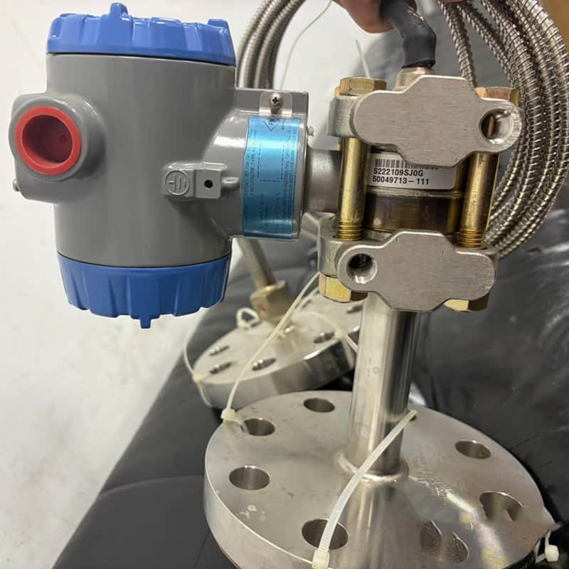
Avoid mounting transmitters directly onto vibrating headers, reciprocating compressor bodies, or high-velocity discharge piping. Position the device body—such as the Honeywell STT650 or STT750 series—remotely on a rigid structural pipe stand or wall bracket outside the primary vibration zone, utilizing a stable DIN-rail or structural mounting base. Reference any comprehensive Honeywell STT850 installation guide documentation for specific unit clearances.
Step 2: Secure Heavy-Duty Brackets and Vibration Dampeners
Mount the instrument using thick, corrosion-resistant brackets coupled with industrial-grade rubber or spring dampeners to absorb high-frequency energy. Secure all bolts with spring washers, split lock washers, or nylon-insert lock nuts to prevent fasteners from backing out under continuous harmonic oscillation.
Step 3: Implement Impulse Line and Capillary Support
Deploy flexible metallic hosing or engineered loop configurations between the process tap and the transmitter inlet to absorb mechanical thermal expansion and vibration shock. Ensure all impulse lines and capillary tubes are anchored rigidly to independent structural supports at regular intervals.
Step 4: Establish Secure Electrical Strain Relief and Ex Compliance
Protect signal wiring by routing cables through heavy-duty industrial cable glands and leaving a controlled service loop near the conduit entry to prevent tension. Following certified Honeywell pressure transmitter wiring and mounting practices guarantees loop stability. If deploying transmitters in hazardous areas (such as Class I, Div. I environments), strictly adhere to certified intrinsic safety specifications and local explosion-proof routing guidelines.
4. Troubleshooting and Maintenance Strategy for High-Vibration Environments
Even with robust installation practices, continuous operation in heavy industrial plants requires proactive maintenance routines to prevent unexpected downtime and ensure preventing vibration damage in field instruments over their lifecycle. For related insights on mitigating common measurement offsets caused by mechanical stress, review our article on Honeywell Pressure Transmitter: Tips for Avoiding Sensor Drift.
Root-Cause Analysis for Vibration-Induced Failures
When diagnostic tools or control room alarms indicate an anomaly, maintenance teams should follow a structured troubleshooting methodology:
Intermittent Signal Loss: Check 24VDC screw terminals and junction box connections. High-frequency harmonic oscillation frequently loosens terminal block screws, creating high contact resistance.
Erratic Output Spikes: Inspect impulse lines or capillary tubing for micro-cracks, fatigue fractures, or unanchored sections slapping against structural steel.
Permanent Calibration Shift: If zero or span drift persists despite software compensation, inspect the mounting bracket for structural micro-fractures, bolt slippage, or degraded rubber dampeners. If you encounter initial setup blocks during your checkout phase, our troubleshooting walkthrough on Honeywell STT850: How to Solve "Configuration Error" During Commissioning provides additional remediation steps.
Preventive Maintenance Schedule
To maintain long-term measurement accuracy and regulatory compliance in high-vibration zones, implement these maintenance intervals:
Monthly Checks: Visually inspect all external mounting hardware, U-bolts, lock washers, and flexible conduit fittings for signs of loosening or fatigue.
Quarterly Diagnostic Audits: Connect via HART or TZC tools to review internal error logs, sensor health metrics, and filter configurations, ensuring noise dampening remains optimal.
Semi-Annual Calibration: Shorten standard 12-month calibration cycles to 6 months in severe vibration service. Perform multi-point verification across low, medium, and high operating ranges to catch linearity drift early, using techniques tailored for how to install transmitter in high vibration service environments.
5. Summary of Best Practices for Extending Instrument Lifespan
Successful deployment of Honeywell transmitters in high-vibration environments requires a systematic methodology spanning the entire lifecycle of installation, calibration, and maintenance.
Installation Phase
Physical Isolation: Prioritize remote mounting to completely isolate the transmitter body from the primary vibration source.
Mechanical Protection: Utilize vibration-dampening brackets, lock washers, and flexible connections to absorb high-frequency residual vibration.
Electrical Protection: Ensure cables feature stress-relief loops and are paired with heavy-duty industrial cable glands.
Commissioning Phase
Parameter Configuration: Optimize damping parameters and digital filter settings via smart communicators or TZC tools.
Calibration & Verification: Execute systematic zero and span calibrations after physical anchoring and stable operation are achieved.
Baseline Archiving: Record all initial configuration parameters and diagnostic data to establish a benchmark for future maintenance.
Maintenance Phase
Structural Inspection: Check for bracket micro-fractures and monitor the aging state of dampening elements during scheduled plant turnarounds.
Connection Audits: Periodically use tools to verify the tightness of cable connectors and the sealing integrity of impulse lines.
Predictive Operations: Continuously leverage the transmitter's embedded diagnostic functions to transition from reactive repairs to predictive maintenance.
Explore More Formats & Join the Discussion:
If you prefer to review this information in alternative formats or want to connect with our engineering community, you can access our resources across multiple platforms:
SlideShare: View and download the structured presentation summary on our Best Practices for Honeywell Transmitters in High-Vibration
Scribd: Read and share the complete technical document on our Technical Guide: Honeywell Transmitter Installation in High-Vibration Plant Environments
LinkedIn: Join the technical conversation, share your industrial automation experiences, and follow our updates on Engineering Guide: Protecting Field Transmitters from Severe Plant Vibration